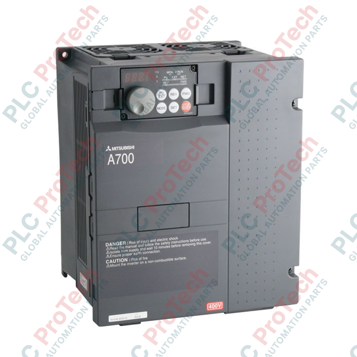
Description
Engineered to provide high-performance speed and torque regulation for three-phase induction motors, the Mitsubishi Electric FR-A740-0.4K-CHT variable frequency drive delivers precise dynamic response in low-power industrial environments. This 0.4 kW inverter belongs to the robust FR-A700 Series, incorporating advanced sensorless vector control technology and localized power optimization. The "CHT" suffix indicates optimized firmware calibration and localized system parameters designed for standard regional grids, facilitating trouble-free integration into modern machinery setups.
Features
- Advanced Real Sensorless Vector Control (RSV) delivers high starting torque and precise speed control without requiring an encoder.
- Built-in miniature PLC functionality allows execution of basic localized control logic, reducing overhead on master controllers.
- Dual overload capacity ratings (LD and ND) allow cost-effective matching to specific system torque profiles.
- Integrated long-life components including cooling fans and capacitors rated for extended deployment lifespans.
- Flexible networking compatibility through dedicated plug-in option cards for CC-Link, Profibus-DP, and DeviceNet.
Applications
- Precision materials handling systems and localized belt conveyors requiring smooth starting torque.
- Industrial ventilation systems, blowers, and low-horsepower centrifugal pump setups.
- Machine tool positioning axes, automated packaging equipment, and packaging line indexers.
- Zonal chemical dosing pumps and dynamic automated mixing apparatuses.
Technical Specifications
| Manufacturer |
Mitsubishi Electric |
| Model Number |
FR-A740-0.4K-CHT |
| Series |
FR-A700 Series |
| Input Voltage Class |
Three-phase 400 V Class (380 to 480 V AC, 50/60 Hz) |
| Applicable Motor Capacity |
0.4 kW (approx. 0.5 HP) |
| Output Frequency Range |
0.2 to 400 Hz |
| Control Algorithms |
V/F Control, Real Sensorless Vector Control, Closed-loop Vector Control (with option card) |
| Enclosure Class |
IP20 (Open Type) |
| Operating Temperature |
-10 to +50 degC (non-freezing) |
| Shipping Weight (Calculated) |
5.5 kg (12.13 lbs) |
| Country of Origin |
Japan / China (Regional OEM Facility) |
Connections and Interfaces
| Terminal Block Label |
Function Assignment |
| R/L1, S/L2, T/L3 |
Three-phase main AC power input (380-480V) |
| U, V, W |
Three-phase variable AC output to the motor terminals |
| P/+, PR |
Dedicated connections for dynamic external braking resistor |
| STF, STR |
Forward and Reverse digital start signal lines |
| SD |
Common terminal ground for external control and sink inputs |
| RJ45 Serial Port |
RS-485 Modbus RTU interface / Parameter unit physical connection |
Empirical Engineering Insights
Alternative Models & Compatibility
The "CHT" variant shares identical dimensions and core power circuitry with standard FR-A740 European or North American models. However, users should note that the default system parameters (such as nominal line frequency defaults and basic digital input logic configuration) are preset to 50Hz and sink logic. If integrating this module as a direct spare part in a system running a non-CHT model, run a full parameter dump comparison via FR Configurator software to ensure matching control configurations.
Application Pitfalls & Engineering Notes
Because of the low-mass heat sink on 0.4 kW models, thermal management is heavily dependent on ambient cabinet airflows. When mounting multiple drives side-by-side, ensure a horizontal spacing of at least 10mm if operating at continuous nominal load. Do not adjust the PWM carrier frequency (Parameter 72) above 12.5 kHz in confined cabinets exceeding 40 degC without implementing a continuous forced-air cooling strategy, as the unit will preemptively trigger a thermal overload (E.THT) fault.
Commissioning & Wiring Tips
To minimize electromagnetic interference (EMI) issues characteristic of PWM frequency outputs, run a shielded four-core motor cable from terminals U, V, and W to the motor, terminating the screen on both ends using high-surface-contact EMC clamps. Never route sensitive low-voltage analog command lines (e.g., 4-20mA speed references) in parallel with main AC supply line or motor line conduits; keep a separation of at least 100mm.
Installation Guidelines
CRITICAL WARNING
Before performing any physical connection or control wiring, isolate the AC power supply. Internal capacitors retain hazardous high-voltage DC charges for several minutes after incoming power is cut. Confirm that the internal charge indicator lamp is completely unlit, and verify with a reliable multimeter that the voltage across DC terminals P/+ and N/- has dropped below 20V DC before starting terminal termination.
1
Mount the drive in a vertical orientation onto a flat, vibration-free panel using standard M4 screws, maintaining at least 50mm clear spacing above and below the unit.
2
Connect the incoming three-phase supply power to mains terminals R/L1, S/L2, and T/L3. Connect the chassis ground to the dedicated Earth connection terminal.
3
Connect the motor power cable leads to the U, V, and W terminals. Verify that no power factor correction capacitors or phase-advance devices are connected to the output path.
4
Turn on the incoming AC supply. Configure the primary parameters (Pr. 1 to Pr. 3 for basic speed limits, and Pr. 9 for motor electronic thermal relay protection) relative to your motor nameplate before initiating motor rotation.