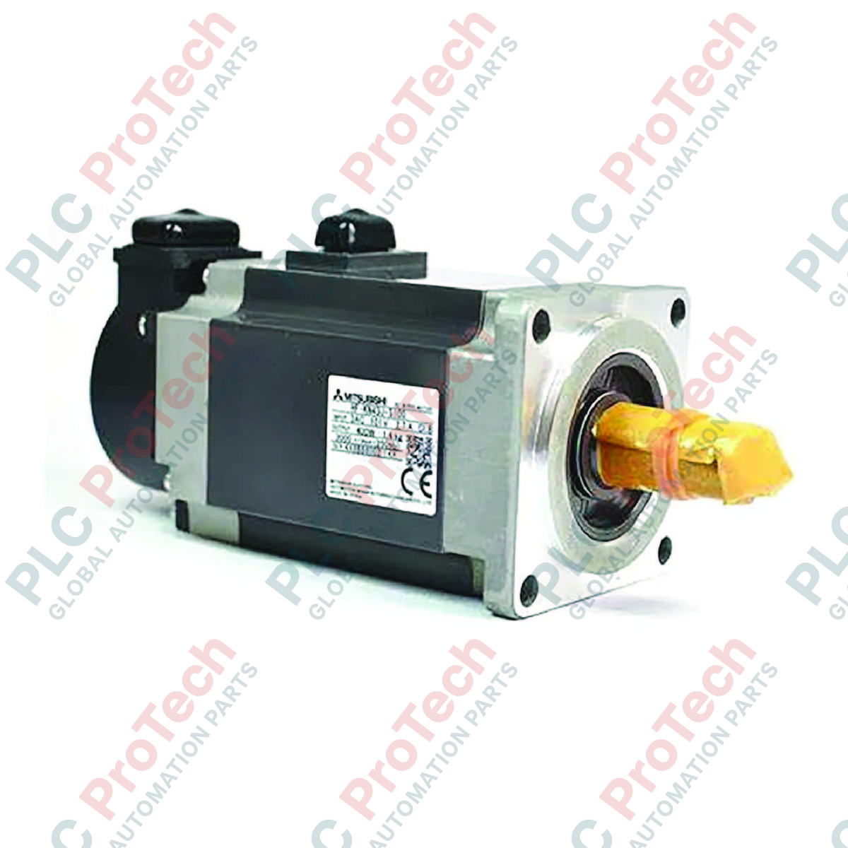
O Mitsubishi Electric HF-SN52BJ-S100, otimizado para aplicações com cargas de alta inércia, oferece posicionamento preciso e controle robusto de torque como parte da família de motores servo AC de alto desempenho da série HF-SN. Este motor de inércia média foi projetado para fornecer operação estável mesmo sob condições de carga flutuantes, tornando-se uma escolha confiável para sistemas de automação industrial.
Principais Características
-
Freio Eletromagnético Integrado: Proporciona retenção segura do eixo durante estados sem energia para evitar queda do eixo vertical ou deslizamento da carga.
-
Vedação de Óleo Instalado de Fábrica: Oferece proteção aprimorada contra a entrada de óleo e lubrificantes na interface do eixo.
-
Classificação Ambiental IP67: Alta resistência a poeira e água (excluindo passagem do eixo) adequada para ambientes industriais severos.
-
Rotor de Inércia Média: Proporciona ajuste estável e controle de movimento suave quando acoplado a cargas mecânicas de alta inércia.
Aplicações Industriais
- Sistemas de manuseio de materiais e transportadores automatizados que requerem freios de retenção.
- Máquinas de embalagem e linhas de montagem automatizadas.
- Mesas de posicionamento X-Y e sistemas de pórtico multi-eixo.
- Máquinas para processamento têxtil e impressão.
Especificações Técnicas
| Fabricante |
Mitsubishi Electric |
| Número do Modelo |
HF-SN52BJ-S100 |
| Série |
Série HF-SN |
| Potência Nominal |
0,5 kW |
| Velocidade Nominal |
2000 rpm |
| Freio Eletromagnético |
Sim (Freio de Retenção) |
| Vedação de Óleo |
Sim |
| Classificação IP |
IP67 (excluindo passagem do eixo) |
| Peso para Envio |
10,5 kg |
Insights Empíricos de Engenharia
Modelos Alternativos & Compatibilidade
O HF-SN52BJ-S100 serve como uma atualização direta para motores antigos da série HC-SF com classificações de potência equivalentes. Ao migrar para este modelo, certifique-se de que os parâmetros do amplificador de servo (especificamente o ID do motor nos drives das séries MR-J4 ou MR-JE) estejam corretamente atualizados para corresponder ao perfil HF-SN, a fim de evitar erros de comutação ou falhas no feedback do encoder.
Armadilhas de Aplicação e Notas de Engenharia
O freio eletromagnético integrado é projetado estritamente como um freio de retenção e nunca deve ser usado para desaceleração dinâmica ou parada de emergência. Ciclos repetidos de frenagem dinâmica causarão desgaste prematuro das placas de atrito, levando à falha na retenção. Além disso, certifique-se de que o selo de óleo esteja lubrificado com uma fina película de óleo durante a instalação para evitar desgaste por funcionamento a seco.
Dicas para Comissionamento e Fiação
Sempre use cabos de par trançado com blindagem dupla para a conexão do encoder para mitigar interferência eletromagnética (EMI) de alta frequência proveniente da saída do inversor PWM. Aterre a estrutura do motor diretamente ao barramento de terra comum do painel de controle usando uma fita de aterramento trançada, grossa e plana, em vez de um fio redondo padrão, para maximizar a dissipação de ruído de alta frequência.
Diretrizes de Instalação
AVISO CRÍTICO: Certifique-se de que todas as fontes de alimentação CA que chegam ao amplificador servo estejam completamente desenergizadas e bloqueadas antes de tentar a instalação ou manutenção. Aguarde pelo menos 15 minutos para que os capacitores internos do barramento descarreguem totalmente. Verifique a tensão zero nos terminais do barramento CC com um multímetro calibrado antes de manusear as conexões de energia do motor.
1
Monte o motor firmemente em uma estrutura metálica rígida e com amortecimento de vibração, garantindo alinhamento axial preciso com a carga acionada para evitar sobrecarga nos rolamentos.
2
Conecte os cabos de alimentação, freio e encoder, garantindo que todos os conectores estejam totalmente encaixados e travados para manter a vedação ambiental IP67.
3
Realize uma verificação manual de rotação do eixo antes de aplicar energia para verificar se não há travamento mecânico ou interferência dentro do acoplamento.