Description
Designed to meet the rigorous demands of multi-axis coordinated motion control, the Mitsubishi Electric MR-J2S-500B delivers high-accuracy closed-loop servo control within the SSCNET synchronous network architecture. Operating at a 5.0 kW rated output capacity, this three-phase AC servo drive interfaces with host motion controllers using high-speed optical fiber communication to eliminate electrical noise and EMI interference. Featuring automatic real-time tuning and resonance suppression, the drive ensures stable mechanical system response even under varying inertia profiles. Built-in dynamic braking and robust overcurrent thermal protections safeguard both the motor and the electrical cabinet environment.
Features
-
5.0 kW Output Rating: Heavy-duty capacity engineered to drive high-inertia AC brushless servo motors.
-
SSCNET Communication (Type B): High-speed optical fiber interface provides synchronized, real-time command processing and reduces field wiring.
-
Adaptive Vibration Suppression: Automatic notch filter adjustments dynamically compensate for mechanical resonance and machine vibration.
-
Integrated Dynamic Brake: Provides rapid, self-contained emergency stopping capabilities without relying on external control power.
-
Comprehensive Safety Architecture: Built-in detection for overcurrent, regenerative overvoltage, overload, and encoder communication faults.
Applications
- High-speed packaging, cartoning, and material handling systems.
- Multi-axis CNC machining centers and precision metal-forming machinery.
- Automated robotic assembly cells and synchronized gantry positioners.
- Coil winding, steel processing, and high-torque web tensioning applications.
Technical Specifications Table
| Parameter |
Value |
| Manufacturer |
Mitsubishi Electric |
| Model Number |
MR-J2S-500B |
| Series Name |
MELSERVO J2-Super |
| Rated Output Capacity |
5.0 kW (5000 Watts) |
| Main Circuit Input Power |
3-phase 200 to 230 VAC, 50/60 Hz |
| Control Circuit Input Power |
1-phase 200 to 230 VAC, 50/60 Hz |
| Control Interface |
SSCNET (Type B Sync Network) |
| Control System |
Sine-wave PWM control / current control system |
| Cooling Type |
Forced fan cooling |
| Ingress Protection Rating |
IP00 (Open Structure) |
| Operating Temperature |
0 to 55 degC (non-freezing) |
| Net Weight |
4.9 kg |
| Shipping Weight (Calculated) |
6.5 kg |
Connections and Interfaces
| Terminal / Port |
Circuit Assignment & Function |
| L1, L2, L3 |
Main circuit 3-phase AC input supply connection |
| L11, L21 |
Control circuit 1-phase AC input supply connection |
| U, V, W |
Servo motor power output phase connections |
| P, C |
External regenerative brake resistor terminals (remove short-bar) |
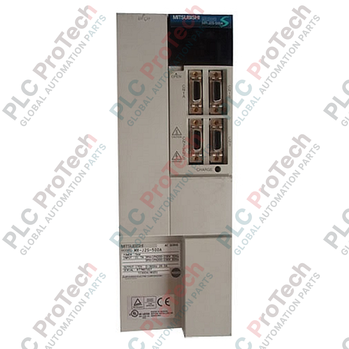
| CN1A |
SSCNET bus connection input (from controller or preceding drive) |
| CN1B |
SSCNET bus connection output (to subsequent drive or terminating connector) |
| CN2 |
Encoder feedback connection (absolute or incremental) |
Empirical Engineering Insights
Alternative Models & Compatibility
The "B" suffix signifies that this amplifier uses the optical SSCNET proprietary network protocol. It is not drop-in compatible with the analog/pulse-train variant (MR-J2S-500A) or the CC-Link positioning model (MR-J2S-500CP). When retrofitting older systems, ensure that the master motion card (such as QD75MH or QD72) supports SSCNET I communication protocols before deploying this drive.
Application Pitfalls & Engineering Notes
Under heavy, high-duty-cycle deceleration profiles, the internal dynamic braking circuit can trigger regenerative overvoltage alarms (AL.30 or AL.33). To mitigate thermal load and avoid premature capacitor wear, remove the jumper between terminals P and D, and wire an external regenerative brake resistor across terminals P and C. Ensure the external resistor meets the minimum Ohm requirement specified in the OEM technical manual.
Commissioning & Wiring Tips
Rotary switch SW1 behind the front flip-down cover sets the physical station axis address. Always configure SW1 with the control circuit power (L11/L21) switched off; the amplifier will not recognize address changes modified during live operations. Ensure the fiber optic connections on CN1A and CN1B do not exceed a bend radius of 25 mm to prevent optical transmission attenuation, which triggers communication link faults.
Installation Guidelines
CRITICAL WARNING: ELECTRICAL SHOCK HAZARD
Isolate both main power (L1, L2, L3) and control power (L11, L21) before starting any wiring or hardware modification. Charge indication lamps on the front face must be completely extinguished before making contact with the electrical terminals. Wait at least 15 minutes post de-energization to allow internal high-voltage capacitors to bleed charge down to a safe level.
1
Vertical Orientation: Mount the amplifier vertically on an unpainted metallic backplate to ensure proper EMI grounding. Maintain a minimum top/bottom clearance of 40 mm and side clearance of 10 mm for correct convection cooling.
2
Power Terminal Torques: Torque all high-power terminal screws (L1, L2, L3, U, V, W) to 1.2 N·m. Loose power connections are a primary cause of localized terminal block overheating and internal drive failure.
3
Grounding: Connect the drive grounding terminal to the protective earth (PE) using a low-impedance copper wire of at least 5.5 mm² cross-section to mitigate electrical noise across the control and optical encoder feedback loops.