Description
Operating as a core motion component within the MELSERVO-J3 architecture, the Mitsubishi Electric MR-J3-200A is a high-performance, digital AC servo amplifier engineered to deliver exceptional dynamic response and positioning accuracy. This 2.0 kW drive utilizes advanced sinusoidal PWM control to regulate current and voltage loops, enabling highly stable torque and velocity control profiles under varying load conditions. It interfaces seamlessly with high-resolution 18-bit absolute or incremental encoders, providing 262,144 pulses per revolution of feedback resolution to eliminate mechanical micro-vibrations and optimize speed constancy. Designed for general-purpose industrial motion networks, this model integrates dedicated pulse-train and analog control interfaces, facilitating straightforward integration with legacy PLCs, stand-alone indexers, and specialized multi-axis motion controllers.
Product Features
-
Dual-Control Interface: General-purpose "A" type configuration supporting high-frequency pulse-train inputs for precision positioning and dual analog inputs for independent speed/torque control loops.
-
Dynamic Frequency Response: Realizes a speed frequency response of 2100 Hz, minimizing loop-cycle latency and drastically reducing settling times during high-duty reversing cycles.
-
Adaptive Vibration Suppression: Embedded dual-frequency vibration filters automatically detect mechanical resonance frequencies and apply real-time suppression to protect physical drive trains and coupling joints.
-
Real-Time Auto-Tuning: Built-in advanced estimation algorithms continuously monitor the load inertia ratio in real-time, dynamically adjusting gain coefficients to maintain system stability under varying load conditions.
-
Absolute Positioning Support: Equipped with standard internal logic to maintain absolute position tracking when paired with compatible absolute encoder backup batteries.
Applications
- High-speed multi-axis pick-and-place gantry robots and material handling systems.
- Precision electronic component insertion machinery and semiconductor processing equipment.
- Feed-axis controls for CNC machining centers, automated milling, and milling auxiliary axes.
- High-speed rotary packaging, horizontal form-fill-seal, and labeling machinery.
- Automotive assembly cell positioners, linear transfer tables, and mechanical stamping presses.
Technical Specifications
| Manufacturer |
Mitsubishi Electric |
| Model Identifier |
MR-J3-200A |
| Product Series |
MELSERVO-J3 |
| Rated Output Power |
2.0 kW |
| Main Circuit Power Input |
3-phase 200 to 230 VAC, 50/60 Hz |
| Control Circuit Power Input |
Single-phase 200 to 230 VAC, 50/60 Hz |
| Rated Output Current |
11.0 A continuous |
| Control Method |
Sine-wave PWM control, current regulation loop |
| Interface Type |
General-Purpose (Analog speed/torque, Command pulse train position) |
| Compatible Motors (Typical) |
HF-SP202, HF-JP203, HC-LP202, HC-UP202, HC-RP203 |
| Cooling Method |
Forced-ventilation cooling fan (internally mounted) |
| Operating Temperature Range |
0 to 55 degC (ambient air, non-freezing) |
| Operating Humidity Limit |
90% RH maximum (non-condensing) |
| Country of Origin |
Japan |
| Shipping Weight (Calculated) |
3.5 kg |
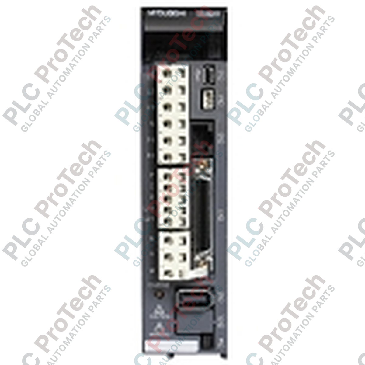
Connections and Interfaces
| Connector / Terminal |
Functional Assignment & Pin Out Description |
| CN1 |
50-pin high-density SCSI interface for analog inputs, differential pulse-train lines, and discrete digital I/O lines (limits, emergency stop, alarms). |
| CN2 |
10-pin interface dedicated to the high-speed serial encoder feedback loop from the servo motor. |
| CN3 |
Communication port supporting personal computer links (MR Configurator software via USB) and connection to external parameter units (RS-422 interface). |
| L1 / L2 / L3 |
High-voltage main power supply input terminals for three-phase AC 200 to 230 VAC. |
| L11 / L21 |
Isolated single-phase 200 to 230 VAC auxiliary power input terminals to keep control/diagnostic logic active when main power is cut. |
| U / V / W |
Three-phase AC power output terminals to the servo motor. Ensure precise phase matching (U to U, V to V, W to W). |
| P+ / C / D |
Terminals for internal and external regenerative brake resistor options. Standard configuration bridges P+ and D for the internal resistor. |
Empirical Engineering Insights
Alternative Models & Compatibility
When replacing legacy MR-J2S-200A models, the MR-J3-200A serves as an excellent upgrade pathway; however, direct plug-and-play is not possible. The control connector pinouts (CN1) are mapped differently, and the encoder connector (CN2) requires a newer serialization interface. Users must employ parameter conversion utilities within the MR Configurator software environment and verify that the target motor's absolute encoder format is fully supported by the newer J3 firmware baseline (particularly for older HC series motors).
Application Pitfalls & Engineering Notes
Thermal management of the 2.0 kW drive requires close observation inside compact electrical enclosures. When installing multiple units adjacent to each other, a minimum horizontal spacing of 10 mm and vertical spacing of 40 mm is required to prevent cumulative heat buildup. If high-inertia cycling is required, monitor parameter PC02 (regenerative load ratio) during commissioning. If the ratio exceeds 100%, the internal regenerative resistor is saturated, and an external regenerative option (such as the MR-RB32 module) must be added to prevent "AL.30" (regenerative overvoltage) faults.
Commissioning & Wiring Tips
To avoid control loop instabilities, command pulse input lines (terminals connected to CN1) must utilize high-quality, individually twisted-pair shielded cables. Ground the overall cable shield to the connector shell on the amplifier side only. When commissioning, verify that the single-phase control power inputs (L11/L21) are energized prior to or simultaneously with the primary three-phase main power (L1/L2/L3); a timing delay in control loop initialization can lead to a transient "AL.E9" (main circuit off) alarm state.
Installation Guidelines
CRITICAL WARNING:
Ensure all primary 3-phase AC power lines (L1/L2/L3) and control power lines (L11/L21) are fully disconnected and locked out. Allow at least 15 minutes for the internal high-voltage DC bus capacitors to discharge. Verify the DC bus voltage across terminals P+ and N- is below 20V DC using a certified digital multimeter before touching any terminal connections.
1
Mount the amplifier vertically on a flat, conductive, and unpainted metallic panel within a dust-free and oil-mist-free industrial enclosure to establish low-impedance high-frequency ground contact.
2
Connect the protective earth (PE) ground wire directly to the dedicated chassis grounding screw before routing high-voltage power lines.
3
Terminate the single-phase control power lines to L11 and L21, then route the main 3-phase power line to L1, L2, and L3 using appropriately sized branch-circuit fuses.
4
Connect the U, V, and W phase cables directly from the amplifier to the motor, ensuring the phase sequence is maintained. Do not connect main utility AC power to these output terminals.
5
Insert the CN2 encoder feedback connector and the CN1 control interface connector, securing all fastening screws to prevent vibration-induced signal interruptions.