Description
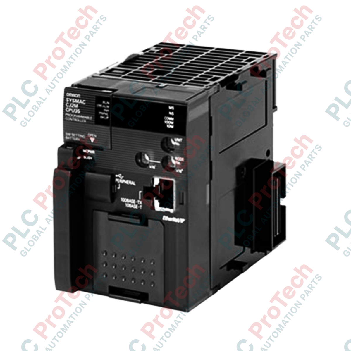
To address modern Ethernet-centric automation requirements, the Omron CJ2M-CPU31 serves as a high-speed central processing unit within the Sysmac CJ-Series platform. This module integrates a dedicated EtherNet/IP port and a dedicated USB programming port directly onto the controller body, eliminating the need for auxiliary network modules. Operating on the modular CJ-system backplane, this unit processes basic instructions at a rate of 0.04 microseconds, providing the throughput necessary for precise packaging, assembly, and synchronized material handling applications. With support for tag-based data links and a modular option board slot, it represents a versatile control core for distributed machine architectures.
Features
- Built-in EtherNet/IP port supporting tag data links, FINS message communications, and direct software connection.
- High-speed processing reaching 0.04 microseconds for basic logic instructions.
- Integrated USB 2.0 peripheral port for direct, high-speed programming and diagnostics with CX-Programmer.
- 5K steps of program capacity and 64K words of Data Memory (DM) to accommodate comprehensive structured logic.
- One free option slot for serial communication (RS-232C/RS-485) or analog I/O expansion boards.
- Scalable architecture supporting up to 40 expansion units across three backplane racks.
Applications
-
Distributed I/O Systems: Managing remote nodes and smart field devices via EtherNet/IP.
-
Packaging and Wrapping Machinery: Executing high-speed sequence control with tight timing margins.
-
Assembly & inspection: Interfacing with vision sensors, RFID systems, and smart sensors.
-
Secondary Automation Nodes: Acting as sub-controllers in automotive assembly plants and water treatment operations.
Technical Specifications Table
| Specification Parameter |
Value / Rating |
| Manufacturer |
Omron |
| Model Number |
CJ2M-CPU31 |
| Product Series |
SYSMAC CJ2M |
| Program Capacity |
5K steps |
| Data Memory Capacity |
64K words (DM: 32K words, EM: 32K words x 1 bank) |
| LD Instruction Execution Time |
0.04 microseconds |
| Max. I/O Capacity |
2,500 points (using CJ expansion racks) |
| Built-in Interface Ports |
1x EtherNet/IP (RJ45), 1x USB 2.0 (Type-B) |
| Option Board Slots |
1 slot (supports CJ2M-MD21x/CIFxx) |
| Current Consumption |
0.70 A at 5 VDC |
| Standards and Certifications |
cULus (Class I Div 2), CE, Lloyd's Register, NK |
| Dimensions (H x W x D) |
90 mm x 62 mm x 84.5 mm |
| Product Net Weight |
0.19 kg |
| Shipping Weight (Calculated) |
1.50 kg (including industrial protective boxing) |
Connections and Interfaces
| Interface Port |
Physical Connection Type |
Functional Assignment |
| EtherNet/IP Port |
Shielded RJ45 Jack |
100Base-TX/10Base-T fieldbus communication, tag data links, and online programming. |
| USB Port |
USB 2.0 Type-B Female |
Local connection point for CX-One / CX-Programmer engineering software. |
| Option Slot |
Internal Board Connector |
Dedicated interface slot for mounting serial communication option boards or pulse I/O cards. |
Empirical Engineering Insights
Alternative Models & Compatibility
When migrating from legacy CJ1M series CPUs (such as the CJ1M-CPU11 or CPU21) to the CJ2M-CPU31, review your user memory allocations. The CJ2M platform utilizes a unified memory structure that allows easier access to variables, but some system-reserved memory addresses (A-words) differ. Although CX-Programmer automatically updates most memory maps during program conversions, physical communication card drivers and custom FINS messaging structures should be verified post-conversion.
Application Pitfalls & Engineering Notes
While the integrated EtherNet/IP port is highly efficient for tag-based data links, heavy cyclic data traffic can influence the CPU overall cycle time. If communication load exceeds 50% of the network card capacity, configure the "EtherNet/IP Port Service Time" in the PLC settings to allocate a fixed execution time slice. This limits communication overhead and prevents unexpected PLC cycle-time extension errors.
Commissioning & Wiring Tips
To prevent communications interruptions caused by electromagnetic interference, always install double-shielded STP Cat5e (or better) industrial Ethernet cables. Ground the functional earth (GR) terminal on the adjacent power supply module to a high-quality electrical ground using copper cabling with a cross-section of at least 2 square millimeters. Never route Ethernet cables inside the same wiring duct as high-voltage motor output phases.
Installation Guidelines
CRITICAL WARNING:
Before installing, removing, or wiring any module within the SYSMAC rack, you must isolate and turn off the main AC or DC incoming power to the system power supply unit. Failure to completely de-energize the assembly can cause backplane voltage surges that permanent destroy the CPU internal silicon architecture or cause unexpected industrial actuator movement.
1
Align the mating connectors on the side of the CPU module and the power supply module, then press the units together firmly.
2
Secure the modules together by locking the yellow slider locks located at the top and bottom of the module housings until they click into place.
3
Mount the locked controller assembly onto a standard 35 mm symmetric DIN rail and verify that both DIN-rail latches are engaged.
4
Connect the functional ground terminal of the adjacent power supply module to your system cabinet ground point.
5
Insert the RJ45 Ethernet communication line and the USB diagnostics cable before powering on the device.