Description
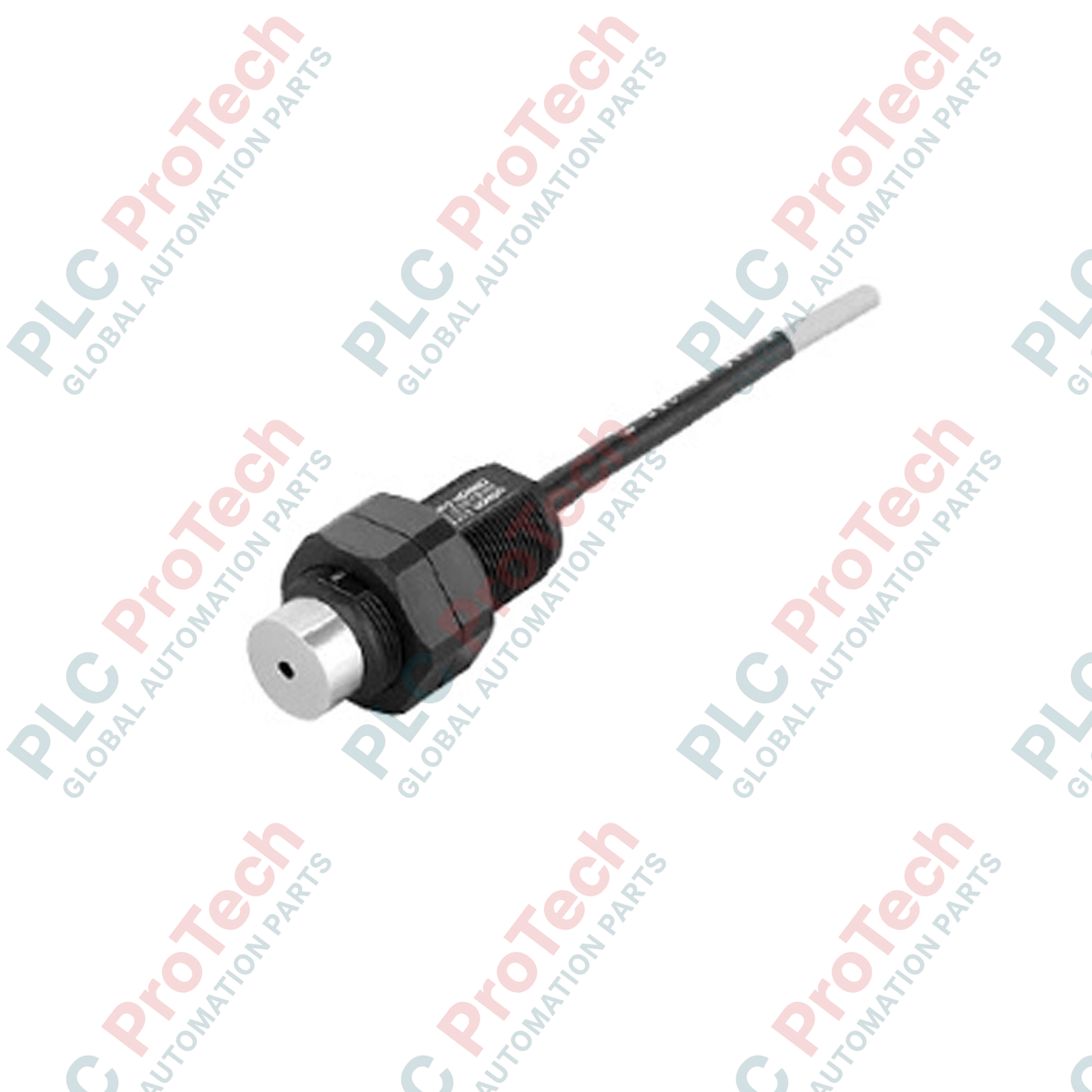
Providing reliable non-contact temperature detection in automated processing environments, the Omron ES1-LP10-N is a high-precision infrared thermosensor optimized for close-range thermal monitoring. Engineered without an integrated laser pointer for deployment in laser-restricted or sensitive industrial zones, this sensor utilizes a high-sensitivity thermopile detection element combined with a premium silicon lens to measure temperatures ranging from -50 to 500 degC. It offers flexible integration options by supporting both standard 12 to 24 VDC industrial field power and direct USB bus power, making it highly versatile for both permanent machine installations and temporary diagnostic setups.
Features
-
Non-Laser Design: Safe for restricted manufacturing areas where laser-emitting alignment devices are prohibited.
-
High-Accuracy Optical Lens: Silicon lens optical system provides a distinct 8 mm diameter target spot at a 100 mm focal distance.
-
Broad Spectral Response: Detects wavelengths between 8 and 14 micrometers, shielding measurement integrity from ambient environmental interference.
-
Dual Power Modes: Runs on a standard 12 to 24 VDC industrial power supply or directly via a USB interface.
-
Rapid Thermal Response: Thermopile technology ensures real-time thermal tracking for dynamic assembly lines.
Applications
- Real-time surface temperature monitoring of molded plastics during ejection.
- Continuous thermal validation of web-fed packaging materials.
- Non-contact monitoring of electrical busbars and distribution panels.
- Process temperature monitoring in food-grade wrapping and sealing operations.
Technical Specifications
| Specification Parameter |
Value / Details |
| Manufacturer |
Omron |
| Model Number |
ES1-LP10-N |
| Detection Element |
Thermopile |
| Lens Material |
Silicon |
| Measurement Temperature Range |
-50 to 500 degC |
| Target Field of View |
8 mm diameter at 100 mm distance |
| Measurement Wavelength |
8 to 14 micrometers (um) |
| Operating Power Supply Voltage |
12 to 24 VDC / USB bus power |
| Allowed Voltage Fluctuation |
95% to 105% of rated voltage |
| Current Consumption |
30 mA maximum (at 24 VDC) |
| Operating Temperature Range |
0 to 55 degC (non-condensing) |
| Operating Humidity Range |
35% to 85% RH (non-condensing) |
| Storage Temperature Range |
-20 to 55 degC |
| Net Weight |
Approx. 0.095 kg (95 grams) |
| Shipping Weight (Calculated) |
1.00 kg |
Empirical Engineering Insights
Alternative Models & Compatibility
The ES1-LP10-N is the non-laser pointer variant of the standard ES1 series. If your installation requires active physical alignment via an optical targeting beam, the companion model (ES1-LP10) featuring a built-in Class 2 laser must be sourced. Ensure configuration software is set up to address the specific model variant, as standard software templates may default to laser-toggle parameters that are ignored by this non-laser hardware revision.
Application Pitfalls & Engineering Notes
Because this sensor relies on non-contact thermopile detection, any physical obstructions—such as dust, oil mist, high humidity, or condensation on the silicon lens—will attenuate the incoming infrared energy, leading to false low-temperature readings. In high-temperature or dusty enclosures, clean purge air should be continuously directed across the lens face. Additionally, ensure the target object fully fills the 8 mm measurement spot; if the target is smaller than 8 mm at a 100 mm distance, the sensor will average background temperatures, introducing severe measurement drift.
Commissioning & Wiring Tips
When powered via 12 to 24 VDC, ensure the field cabling is shielded and that the shield is grounded at a single, clean point in the control panel. Running the low-voltage sensor lines in the same wireway as high-current motor controls or variable frequency drives (VFDs) can introduce electromagnetic noise, corrupting the microvolt-level internal signals of the thermopile element.
Installation Guidelines
CRITICAL WARNING
Isolate and lock out all 12 to 24 VDC external power sources prior to initiating mounting or wire termination activities. Do not attempt to wire the sensor while USB connection is active to avoid potential ground loop damage to the diagnostic host.
1
Mount the sensor body to a stable, vibration-damped bracket ensuring the silicon lens is exactly 100 mm perpendicular to the target surface for an optimal 8 mm spot calculation.
2
Connect the dedicated sensor cable to the terminals, verifying the voltage remains within the 95% to 105% tolerance band to avoid internal thermal drift or component wear.
3
Ensure the silicon lens is clean and completely free of manufacturing residues or fingerprints. Wipe only with clean, non-abrasive optical tissues if service is required.