Description
Providing critical measurement precision in standard industrial control panels, the Omron H7CX-AWSD-N functions as a highly adaptable 6-digit multifunction counter and tachometer. This device integrates multiple counting modes—including 1-stage counting, 2-stage counting, batch counting, dual counting, and tachometer functions—into a unified 1/16 DIN housing. Operating on a low-voltage DC range, it provides reliable performance for high-speed tracking, batch processing, and rotational speed monitoring in demanding automation environments.
Key Features
-
Multifunctional Versatility: Configurable as a 1-stage counter, 2-stage counter, total and preset counter, batch counter, dual counter, or high-accuracy tachometer.
-
Dual-Stage Control: Equipped with a 2-stage setting (Type W) to trigger distinct pre-warn and final-stop control actions.
-
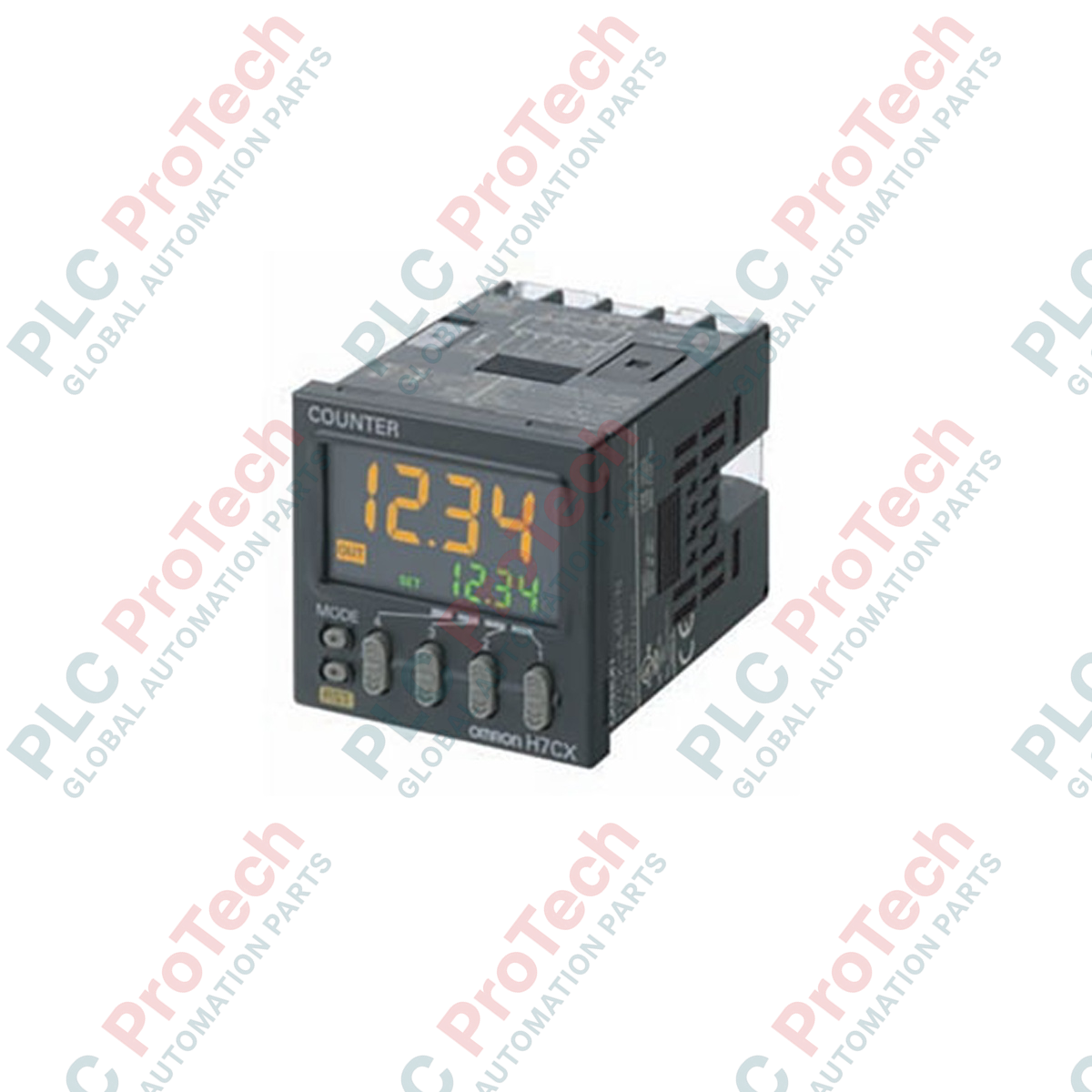
6-Digit High-Visibility Display: Negative transmissive LCD with bright backlighting for clear real-time monitoring of process values (PV) and set values (SV).
-
Selectable Input Speeds: High-speed electronic input tracking up to 10 kHz, or low-speed mechanical switch filtering at 30 Hz.
-
Transistor Outputs: Robust solid-state transistor outputs designed for rapid switching cycles and long operational life.
Industrial Applications
-
High-Speed Packaging Lines: Precise container and batch counting with immediate transistor actuation.
-
Conveyor Control Systems: Dynamic speed calculation and tachometer feedback for motor synchronization.
-
Cut-to-Length Machinery: Dual-stage preset control for deceleration and final shearing operations.
-
Assembly Verification: Dual counter and totalizer operation to verify yield metrics and batch totals.
Technical Specifications
| Parameter |
Specification Value |
| Manufacturer |
Omron |
| Model Code |
H7CX-AWSD-N |
| Configuration Type |
A (Standard Type) |
| Power Supply Voltage |
12 to 24 VDC (Permissible ripple: 20% max.) |
| Number of Digits |
6 digits (-99999 to 999999) |
| Pre-scale Function |
0.001 to 99.999 |
| Control Settings |
2-stage setting (W) |
| Output Type |
Transistor Output (NPN / PNP configurable) |
| Connection Method |
Screw Terminals (M3.5) |
| Physical Form Factor |
1/16 DIN (48 mm x 48 mm panel cutout) |
| Operating Ambient Temp |
-10 to 55 degC (with no icing or condensation) |
| Shipping Weight (Calculated) |
0.35 kg |
| Package Dimensions (Calculated) |
11.0 cm x 8.5 cm x 7.5 cm |
Empirical Engineering Insights
Alternative Models & Compatibility
The "H7CX-AWSD-N" features a shorter physical housing compared to older generation legacy "H7CX-AWSD" models. This reduced-depth design allows for installation in shallow control enclosures. Key terminals and internal configuration parameter maps remain fully backward-compatible, enabling direct field swaps with minimal downtime.
Application Pitfalls & Engineering Notes
When configuring the unit for maximum 10 kHz counting speeds, ensure that solid-state sensors (e.g., proximity or photoelectric sensors) are utilized. Applying mechanical contact switches (like microswitches or limit switches) at high frequency settings will cause contact bounce (chatter) to be counted as valid pulses. For dry contacts, always set the input speed parameter to 30 Hz to activate the internal digital noise filter.
Commissioning & Wiring Tips
Isolate input signal lines from high-voltage AC power lines and motor drive cables to prevent electromagnetic coupling. Use shielded twisted-pair (STP) wiring for CP1, CP2, and Reset inputs. Ground the shield only at a single point near the control cabinet ground terminal to eliminate ground loop interference on DC-powered units.
Installation Guidelines
CRITICAL WARNING
Turn off and lock out all upstream electrical power sources before attempting installation, wiring, or maintenance on this unit. Verify the model rating matches your local supply voltage (12 to 24 VDC) prior to energization. Applying AC line voltage to this DC model will result in catastrophic failure and permanent hardware damage.
1
Prepare a standard 1/16 DIN panel cutout measuring 45 mm x 45 mm. Mount the waterproof packing gasket onto the front bezel if liquid-tight integrity (IP66) is required.
2
Insert the counter through the panel cutout and slide the mounting bracket over the rear body of the unit. Tighten the securing screws evenly until the housing sits flush with the panel surface.
3
Terminate wiring onto the back-panel M3.5 screw terminals using insulated crimp ring or fork terminals. Ensure terminal screws are torqued to approximately 0.5 to 0.6 N-m to maintain secure electrical contact.