Description
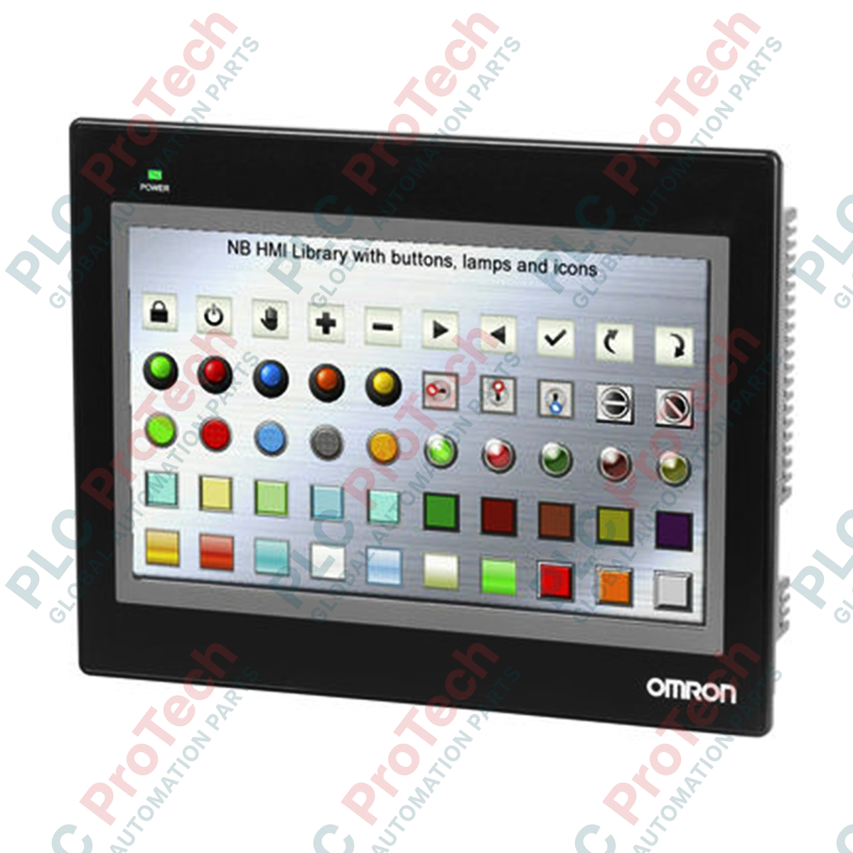
Integrating directly into modern industrial control topologies, the Omron NB10W-TW01B programmable terminal delivers robust human-machine interface performance via a wide 10.1-inch TFT touchscreen. Operating on a nominal 24V DC input, this unit bridges the gap between operators and PLCs using a brilliant 65,536-color display backed by long-life LED illumination. The terminal features 128 MB of internal memory, facilitating complex screen hierarchies, high-resolution graphic elements, and extensive recipe storage without performance degradation.
Equipped with comprehensive physical interfaces, this HMI facilitates concurrent communications across Ethernet, RS-232C, and RS-422/485 serial buses. Built-in USB Host and Client ports support efficient project updates, diagnostic logging, and peripheral connection. Built for harsh factory floors, the front panel achieves IP65 protection, preventing dust ingress and water jet disruptions during washdown cycles.
Key Features
-
High-Resolution Display: 10.1-inch TFT LCD with 800 x 480 WVGA resolution and 65,536-color rendering.
-
Multi-Channel Connectivity: Embedded RJ-45 Ethernet port, RS-232C, and RS-422/485 serial ports for multi-PLC networks.
-
Expanded Storage Capacity: 128 MB internal flash memory for screen layouts, historical logging, and system data.
-
Dual USB Interfaces: USB Host (Type A) for memory stick data transfers and USB Client (Type B) for high-speed programming.
-
Industrial Environmental Protection: Front panel IP65 rating ensures resilience against liquid and particulate contamination.
Applications
-
Packaging Machinery: Real-time monitoring of multi-axis systems, recipe selection, and alarm logging.
-
Water and Wastewater Treatment: Decentralized process visualization, flow monitoring, and remote pump control stations.
-
Material Handling Systems: Conveyor coordination displays, sorting diagnostics, and speed-override controls.
-
HVAC and Building Automation: Centralized environmental monitoring, zone controls, and daily schedule management.
Technical Specifications
| Parameter |
Specification |
| Manufacturer |
Omron Corporation |
| Model Number |
NB10W-TW01B |
| Display Size / Type |
10.1-inch TFT LCD (Widescreen) |
| Resolution |
800 x 480 Pixels (WVGA) |
| Display Colors |
65,536 Colors |
| Backlight Type / Lifetime |
LED / 50,000 Operating Hours (at 25 degC) |
| Input Supply Voltage |
24V DC (Allowable Range: 20.4 to 27.6 VDC) |
| Power Consumption |
14W Maximum |
| Internal Memory Capacity |
128 MB (Screen data storage) |
| Ethernet Communications |
1x RJ-45 (10/100 Base-T) |
| Serial Communications |
COM1 (RS-232C), COM2 (RS-422/RS-485) |
| USB Ports |
1x USB Host (USB 2.0), 1x USB Client (USB 2.0) |
| Front Panel Protection |
IP65 (Dust-proof, Water jet resistant) |
| Ambient Operating Temperature |
0 to 50 degC |
| Physical Dimensions (W x H x D) |
268.8 mm x 210.8 mm x 54.0 mm |
| Panel Cutout Dimensions |
258.0 mm x 200.0 mm |
| Shipping Weight (Calculated) |
2.15 kg (packaged unit) |
| Package Dimensions (Calculated) |
310 mm x 260 mm x 110 mm |
| Country of Origin |
China |
Connections and Interfaces
| Port / Connector |
Pin / Interface Type |
Function / Signal Assignment |
| COM1 Port |
9-pin D-Sub Male (RS-232C) |
Pin 2: SD (TXD), Pin 3: RD (RXD), Pin 9: SG (Signal Ground) |
| COM2 Port |
9-pin D-Sub Female (RS-422/485) |
Pins 1 & 6: SDB+ / RDB+, Pins 2 & 7: SDA- / RDA-, Pin 9: SG |
| Ethernet Port |
RJ-45 (10/100Base-T) |
Network configuration, Modbus/TCP, and high-speed project download |
| USB Slave |
USB Type B |
Direct configuration connection to PC running NB-Designer |
| USB Host |
USB Type A |
Firmware extraction, runtime application updates, CSV data log collection |
| Power Input Terminal |
3-pin Screw Terminal |
Pin 1: 24V DC (+), Pin 2: 0V (-), Pin 3: Functional Ground (FG) |
Empirical Engineering Insights
Alternative Models & Compatibility
The NB10W-TW01B represents the flagship wide-format display within Omron's NB Series, offering significantly expanded interface options compared to smaller variants (such as the NB3W or NB5W). If migrating from older NS-Series or NQ-Series panels, please note that project conversion requires manual element-mapping inside NB-Designer, as graphics databases are not directly backward-compatible. System developers should use NB-Designer Version 1.3 or later to ensure appropriate driver allocation for modern Omron Sysmac NJ/NX controller communications.
Application Pitfalls & Engineering Notes
A common industrial pitfall involves communication interruptions when integrating the serial ports (COM1/COM2) with non-Omron controllers. The internal grounding of the RS-422/485 port is shared with the logic system ground; consequently, if substantial potential differences exist between the HMI and the controller chassis, serial driver failure can occur. High-frequency electrical noise from nearby variable frequency drives (VFDs) can also interfere with touch inputs or communication stability. Standard panel isolation mounting is highly recommended under these conditions.
Commissioning & Wiring Tips
When downloading configuration data over USB, verify that the USB driver has been correctly installed in Windows Device Manager, as the NB Series utilizes a proprietary virtual COM port assignment. For remote updates via Ethernet, ensure that the static IP address, subnet mask, and gateway address allocated within the project database correspond exactly to the on-site physical network architecture. Use a shielded, twisted-pair category 5e or 6 Ethernet cable for all industrial field runs.
Installation Guidelines
CRITICAL WARNING: Prior to attempting physical installation, panel mounting, or electrical terminal connection, confirm that all upstream power systems are completely de-energized and locked out. Do not hot-plug power supply connectors or serial communication cables under load to prevent electrical arcing, controller damage, or physical injury.
1
Prepare a precise rectangular cutout in the enclosure door measuring 258.0 mm (W) x 200.0 mm (H). Remove any sharp burrs or structural distortions along the cutout edges to ensure a continuous sealing seat.
2
Verify that the continuous rubber gasket is correctly seated in the groove on the rear perimeter of the HMI bezel. This gasket is vital for securing the IP65 fluid protection rating.
3
Insert the HMI through the front cutout of the panel door. Fit the provided mounting brackets into the dedicated slots around the sides of the terminal housing.
4
Tighten the mounting bracket screws evenly to a recommended torque of 0.5 to 0.6 N-m. Avoid over-tightening to prevent plastic casing deformation or structural damage to the screen assembly.
5
Connect a dedicated 24V DC power source to the 3-pin input terminal block. Attach a minimum 2.0 mm² copper conductor from the functional ground (FG) terminal to the central system ground terminal.