Description
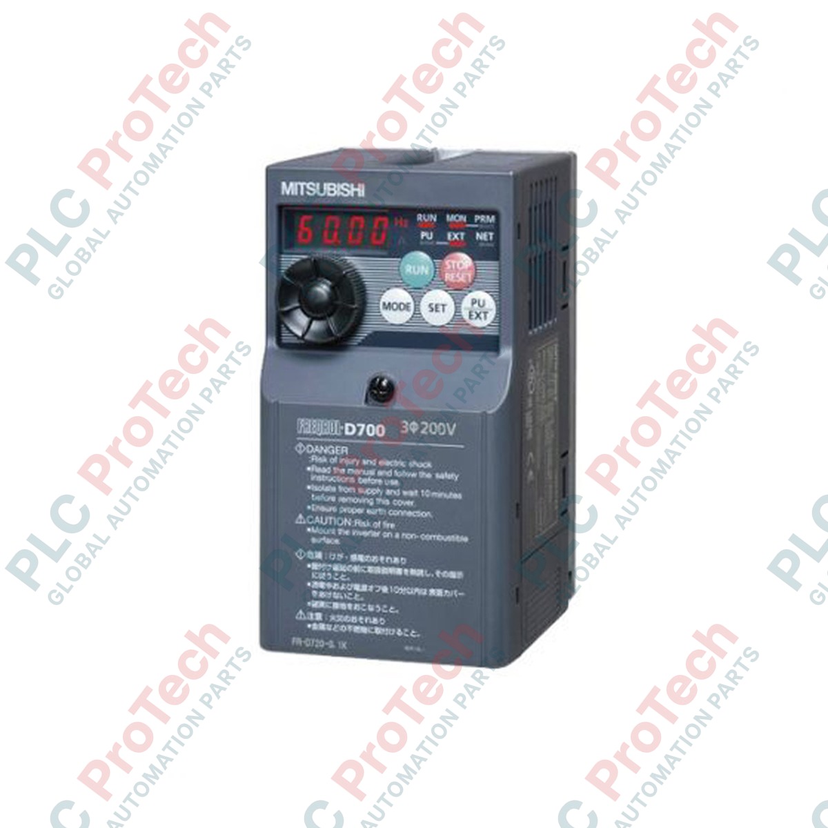
Engineered to deliver high-performance motor speed control in a space-saving envelope, the Mitsubishi Electric FR-D720-7.5K is a micro-drive variable frequency inverter rated for 7.5 kW applications. This three-phase 200V class controller integrates advanced sensorless vector control and a built-in digital setting dial to provide exceptional torque performance at low speeds. Ideal for heavy-duty industrial automation applications, it features comprehensive safety and diagnostic mechanisms, making it a reliable solution for demanding machine-level speed regulation.
Key Features
-
High Torque Generation: Provides 150% torque at 1 Hz when using general-purpose magnetic flux vector control.
-
Built-in Digital Dial: Facilitates easy parameter adjustment, monitoring, and debugging directly from the front faceplate.
-
Spring-Clamp Control Terminals: Delivers high vibration resistance and maintenance-free electrical connections.
-
Integrated Safety Function: Features a hardware-based safe torque off (STO) input for compliance with machine safety regulations.
-
Excellent Overload Capacity: Rated for up to 150% overload for 60 seconds and 200% for 0.5 seconds.
Industrial Applications
-
Conveyor and Material Handling Systems: Precise acceleration control and multi-speed operation settings.
-
Packaging and Bottling Machines: Rapid start/stop cycles with high dynamic response.
-
Centrifugal Pumps and Exhaust Fans: Energy-saving V/F control profiles with automatic PID tuning.
-
Machine Tool Spindles: Stable speed maintenance under varying mechanical loads.
Technical Specifications
| Specification Parameter |
Value |
| Manufacturer |
Mitsubishi Electric |
| Model Number |
FR-D720-7.5K |
| Series Name |
FR-D700 Series |
| Applicable Motor Capacity |
7.5 kW |
| Rated Capacity |
12.7 kVA |
| Rated Current |
31.8 A |
| Overload Current Rating |
150% for 60 seconds, 200% for 0.5 seconds (inverse-time characteristics) |
| Rated Output Voltage |
Three-phase, 200 to 240 V AC |
| Rated Input AC Voltage/Frequency |
Three-phase, 200 to 240 V AC, 50 Hz / 60 Hz |
| Permissible AC Voltage Fluctuation |
170 to 264 V AC, 50 Hz / 60 Hz |
| Permissible Frequency Fluctuation |
+/- 5% |
| Power Supply Capacity |
17.0 kVA |
| Regenerative Braking Torque |
20% maximum |
| Protective Structure |
Enclosed type (IP20, JEM1030) |
| Cooling System |
Forced air cooling (internal cooling fan) |
| Net Unit Weight |
3.6 kg |
| Shipping Weight (Calculated) |
6.0 kg |
Connections and Interfaces
| Terminal Marker |
Function and Assignment |
| R/L1, S/L2, T/L3 |
Three-phase AC power input connection |
| U, V, W |
Three-phase AC motor output connection |
| P/+, PR |
External brake resistor connection point |
| STF, STR |
Forward start (STF) and Reverse start (STR) control signals |
| SD, PC |
Common terminal (SD) and external 24 V DC power common (PC) |
| 10, 2, 4 |
Analog input terminals for speed commands (potentiometer / 0-10 V / 4-20 mA) |
Empirical Engineering Insights
Alternative Models & Compatibility
When migrating legacy systems utilizing older Mitsubishi FR-S500 or FR-E500 series drives, parameter sets must be converted using the FR Configurator software. The physical footprint of the FR-D720-7.5K is highly compact; however, mounting hole dimensions differ from legacy models, making a mounting adapter plate necessary for direct panel replacement. Verify the firmware compatibility version if cascading drives over RS-485 Modbus networks, as older firmware versions may require explicit node polling delays.
Application Pitfalls & Engineering Notes
Operating the FR-D720-7.5K at low frequencies (below 15 Hz) under heavy load conditions dramatically reduces the cooling efficiency of standard self-cooled motors. Under these conditions, specify an inverter-duty motor with independent blower cooling or derate the drive. Note that the internal regenerative braking torque limit is 20%. Applications involving high-inertia vertical loads or cyclic decelerations will cause DC bus overvoltage faults (E.OV3) unless an external braking resistor is properly configured and the PX-PR jumper is removed.
Commissioning & Wiring Tips
To eliminate electromagnetic interference (EMI) affecting adjacent control instrumentation, install a dedicated line noise filter on the input side of the drive. The control terminals are of the spring-clamp variety; ensure that control cables are stripped to exactly 6 mm and use wire ferrule terminals for a highly reliable gas-tight seal. Configure parameter 79 (Operation Mode Selection) to define whether command signals originate from the integrated PU keypad, the RJ45 Modbus-RTU port, or the physical control terminals.
Installation Guidelines
CRITICAL SAFETY WARNING
Isolate and lock out the main AC power source before commencing physical installation. Internal DC bus capacitors hold lethal residual voltage. Wait a minimum of 10 minutes after disconnecting power, and measure across terminals P/+ and N/- using a high-voltage multimeter to verify the voltage is below 45 V before handling terminals.
1
Mount the drive vertically inside an IP20 or higher enclosure. Ensure at least 50 mm clearance above and below, and 10 mm clearance on either side of the chassis to allow unimpeded convection airflow from the internal fan.
2
Connect the physical ground (PE) wire directly to the drive chassis grounding terminal before routing power lines. Use separate, short, low-impedance ground cables to minimize EMI propagation.
3
Wire three-phase input power to terminals R/L1, S/L2, and T/L3. Wire the motor cables to output terminals U, V, and W. Do not cross-connect input power lines to the output terminals, as this causes catastrophic damage to the internal IGBT module.