Description
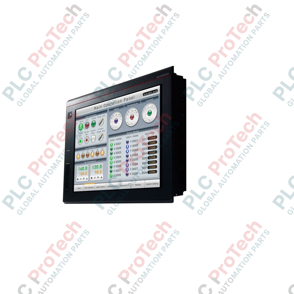
Engineered for seamless integration into high-performance industrial control architectures, the Mitsubishi Electric GT2508-VTBA represents a reliable, mid-range visualization solution within the GOT2000 Series. Featuring an 8.4-inch TFT color LCD with VGA resolution (640 x 480 dots), this Graphic Operation Terminal delivers exceptional visual clarity and responsive control for demanding factory floor environments. The display supports up to 65,536 colors, enabling detailed graphical schematics, alarm histories, and real-time trend graphs. Operated via an analog resistive touch film, the interface accommodates precise multi-touch control and gestures even while operators wear industrial gloves.
This HMI operates on a universal AC power supply rating of 100-240 VAC, ensuring global compatibility across diverse electrical grids. Built-in communications include Ethernet, RS-232, and RS-422/485 serial ports, allowing direct communication with PLCs, variable frequency drives, and servo systems without requiring additional communication modules. The black frame design and IP67F-rated front panel ensure long-term durability when panel-mounted in environments exposed to dust, oil mist, and water spray.
Key Features
-
Vibrant 8.4-inch TFT Display: 640 x 480 pixel VGA resolution with high-intensity backlighting and 65,536 display colors.
-
Analog Resistive Touch Panel: High-precision touch detection supporting single-point and functional gesture operations.
-
Global AC Power Input: Wide input range of 100 to 240 VAC (50/60 Hz) facilitates worldwide deployment.
-
Comprehensive Connectivity: Built-in interfaces including Ethernet, RS-232, RS-422/485, USB Host (Type A), and USB Device (Mini-B) for seamless data transfer and programming.
-
Expandable Storage: Dedicated SD memory card slot for project backups, data logging, and system firmware storage.
-
Robust Environmental Protection: IP67F front-panel rating ensures resistance against liquid ingress, dust, and harsh industrial environments.
Applications
-
Automotive Assembly Lines: Real-time process monitoring, machine status visualization, and safety system oversight.
-
Water and Wastewater Treatment: Clear display of pump controls, valve configurations, and system-wide telemetry.
-
Packaging and Material Handling: Local parameter adjustment, alarm diagnostic management, and high-speed cycle time tracking.
-
Food and Beverage Processing: Washdown-resistant panel mounting for recipe configuration and ingredient batching control.
Technical Specifications
| Manufacturer |
Mitsubishi Electric |
| Model Number |
GT2508-VTBA |
| Series Name |
GOT2000 (GT25) |
| Display Type |
TFT Color LCD |
| Screen Size |
8.4 inch (21.3 cm) diagonal |
| Resolution |
VGA (640 x 480 dots) |
| Display Size (W x H) |
170.9 mm x 128.2 mm |
| Touch Panel Type |
Analog resistive film |
| Frame Color |
Black |
| Supply Voltage |
100 to 240 VAC |
| Input Frequency |
50 / 60 Hz (+/- 5%) |
| Power Consumption |
Maximum 41 W (or less) |
| Panel Cutout (W x H) |
227 mm x 176 mm |
| External Dimensions (W x H x D) |
241 mm x 194 mm x 52 mm |
| Weight (Excluding Brackets) |
1.5 kg |
| Shipping Weight (Calculated) |
2.5 kg |
| Package Dimensions (Calculated) |
310 mm x 260 mm x 120 mm |
Connections and Interfaces
| Interface Port |
Functional Specifications |
| Ethernet Port |
1 Channel (RJ45 connector), 10BASE-T/100BASE-TX for network and controller integration. |
| RS-232 |
1 Channel (D-Sub 9-pin male), transmission speeds up to 115,200 bps. |
| RS-422/485 |
1 Channel (D-Sub 9-pin female), for multi-drop connections to PLCs and temperature controllers. |
| USB Host |
1 Channel (Type-A USB 2.0 High-Speed) for connecting USB storage devices or keyboards. |
| USB Device |
1 Channel (Mini-B USB 2.0 High-Speed) for PC transfer of project screens and program debugging. |
| SD Card Slot |
1 Slot (SDHC compatible) for logging system operational data and storing screen layout backups. |
Empirical Engineering Insights
Alternative Models & Compatibility
When replacing legacy GT15 or GT16 series 8.4-inch HMIs with the GT2508-VTBA, confirm the physical cabinet cutout. While outer dimensions and cutout sizes are matching in most instances, the back-panel protrusion depth differs slightly. Furthermore, screen data created on GT Designer2 must be upgraded to GT Works3 (version 1.100E or later) to match the higher hardware specifications and updated communications libraries of the GOT2000 series platform.
Application Pitfalls & Engineering Notes
In enclosed non-ventilated control panels, avoid mounting this display directly above high-heat emitters such as variable frequency drives or large magnetic contactors. Maintain a minimum vertical clearance of 100 mm to ensure internal convection currents prevent the HMI's ambient operating environment from exceeding 55 degrees Celsius. Exceeding this thermal threshold accelerates the degradation of the LED backlight and can lead to display flicker.
Commissioning & Wiring Tips
Always route the HMI main AC power line through a dedicated isolation transformer if the facility grid experiences severe switching surges or high-frequency line noise from nearby high-frequency machinery. To prevent serial and Ethernet communication dropouts, ensure the functional ground (FG) terminal on the power supply block is connected directly to a clean Class D ground plane (100 ohms or less) using a dedicated 2 mm square or thicker ground lead.
Installation Guidelines
CRITICAL WARNING:
Before initiating physical mounting or electrical terminations, ensure the primary main power breaker feeding the panel is locked and tagged out. Verify the absence of AC potential using a certified voltage tester to prevent accidental electrical shock or damage to the internal processing boards.
1
Prepare the mounting panel cutout precisely to 227 mm x 176 mm. Deburr all cut edges to ensure the front-panel gasket seats evenly against the mounting surface.
2
Ensure the polyurethane waterproofing gasket on the rear of the bezel is clean, continuous, and free of dirt. Slide the HMI into the panel opening from the front.
3
Install the provided metal mounting brackets into the top and bottom slots of the bezel. Progressively torque the mounting screws to 0.36 N-m in a diagonal sequence to secure a uniform seal against water ingress.
4
Wire the 100-240 VAC power input terminal block using ring terminals with insulation sleeves. Apply a tightening torque of 0.5 to 0.8 N-m to the terminal screws. Connect the functional ground (FG) terminal immediately to earth ground.