1 จาก 1

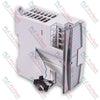
Omron CJ1W-AD041-V1 CJ Series Analog Input Unit

Omron CJ1W-AD041-V1 CJ Series Analog Input Unit

Only 8 item(s) left in stock
  • Manufacturer: Omron

  • Product No.: ÿCJ1W-AD041-V1

  • Country of origin:ญี่ปุ่น

  • Product Type: Analog Output Modules

  • Payment: T/T, Western Union

  • Weight: 1500g

  • Dimensions: 125 x 105 x 35 mm

  • Shipping port: Xiamen

  • Warranty: 12 months

ปริมาณ
ดูรายละเอียดทั้งหมด

Description

Integrating seamlessly into Omron Sysmac CJ-series PLCs, the Omron CJ1W-AD041-V1 provides high-density, precise analog-to-digital conversion across four physical input channels. This module processes voltage and current field transmitter signals, translating physical variables into highly accurate digital data blocks. Its backplane-driven processor supports advanced signal scaling, peak-hold execution, and customized input filtration algorithms directly inside the memory allocation table, eliminating the need for complex ladder-logic averaging routines.

Features

  • Four Selectable Channels: Individual configuration per channel for current (4 to 20 mA) or voltage (1 to 5 V, 0 to 5 V, 0 to 10 V, -10 to +10 V) inputs.
  • High-Speed A/D Conversion: Configurable conversion speeds reaching up to 250 microseconds per point in high-speed mode.
  • Selectable Resolution Modes: Offers standard 1/4000 resolution or high-resolution 1/8000 mode for ultra-precise process variable tracking.
  • Detachable Terminal Block: Features an 18-point detachable M3 screw terminal block, enabling swift module replacements without re-wiring.
  • Built-In Diagnostics: Real-time detection of input wire disconnection, over-range levels, and internal hardware faults.

Applications

  • Chemical processing and multi-loop temperature tracking via 4-20 mA transmitters.
  • Water and wastewater monitoring involving volumetric flow and pressure transmitters.
  • Variable frequency drive (VFD) speed-feedback control systems.
  • Precise packaging and tension-control systems utilizing load cells and signal conditioners.

Technical Specifications

Parameter Specification Values
Manufacturer Omron Industrial Automation
Model Number CJ1W-AD041-V1
Product Series CJ Series (CJ1G, CJ1H, CJ1M, CJ2M, CJ2H)
Number of Analog Inputs 4 Channels
Input Voltage Ranges 0 to 5 V, 1 to 5 V, 0 to 10 V, -10 to +10 V
Input Current Ranges 4 to 20 mA
Resolution Options 1/4000 (Standard), 1/8000 (High-Resolution Mode)
Conversion Time 1.0 ms/point max. (Standard), 250 microsec/point max. (High-Speed)
Accuracy (25 degC) Voltage: +/-0.2% of FS; Current: +/-0.4% of FS
Channel-to-Channel Isolation None (Common ground plane)
Backplane Bus Isolation Photocoupler isolated between input terminals and CPU internal logic
Internal Current Consumption 0.42 A at 5 VDC (Backplane rail)
External Wiring Terminal 18-point detachable terminal block (M3 screws)
Standards & Approvals CE, UL (Class I Div 2), NK, Lloyd's
Country of Origin Japan
Shipping Weight (Calculated) 0.32 kg
Package Dimensions (Calculated) 125 x 105 x 35 mm

Connections and Interfaces

Terminal No. Signal Label Description
1 V IN 1 Voltage Input Terminal, Channel 1
2 I IN 1 Current Input Terminal, Channel 1
3 COM 1 Common Terminal, Channel 1
4 V IN 2 Voltage Input Terminal, Channel 2
5 I IN 2 Current Input Terminal, Channel 2
6 COM 2 Common Terminal, Channel 2
7 V IN 3 Voltage Input Terminal, Channel 3
8 I IN 3 Current Input Terminal, Channel 3
9 COM 3 Common Terminal, Channel 3
10 V IN 4 Voltage Input Terminal, Channel 4
11 I IN 4 Current Input Terminal, Channel 4
12 COM 4 Common Terminal, Channel 4
13 to 17 NC No Connection (Do not wire)
18 SLD Shield Terminal (Internal system ground)

Empirical Engineering Insights

Alternative Models & Compatibility

The "V1" suffix indicates critical updates over the legacy non-V1 module. It introduces the high-resolution mode (1/8000 conversion) and reduces overall conversion times down to 250 microseconds per channel. The module is fully backward compatible; however, if you are upgrading from an older version in a system that utilized specific unit settings, you must reconfirm the I/O allocation mapping in CX-Programmer to ensure the CPU can register the newer features.

Application Pitfalls & Engineering Notes

This unit features non-isolated input channels, meaning all four channels share a common internal ground plane. If you feed analog signals from devices powered by different external DC supplies, ground-loop offset voltages will distort the analog readings or potentially trigger hardware faults on the module. For isolated channels, choose the CJ1W-AD042 or add signal isolators externally on each loop.

Commissioning & Wiring Tips

Always route the analog signal cabling away from high-voltage motor power cables to mitigate EMI noise coupling. Connect the shield line of the twisted-pair cable exclusively to the SLD terminal (Pin 18) on the module's terminal block. Unused channels must be explicitly disabled in the software configuration; otherwise, they will float and cause the PLC's internal error flags to cycle unexpectedly.

Installation Guidelines

CRITICAL WARNING

Do not insert or remove the CJ1W-AD041-V1 module from the PLC backplane while the rack is powered. De-energize the main control supply completely and allow all internal bus charges to bleed down to zero before handling. Live insertion will damage the backplane interface ASIC and corrupt the memory tables within the CPU module.

1
Align the structural hook on the upper section of the module with the slot on the PLC backplane. Rotate the module downwards until it seats flush.
2
Secure the unit by locking the yellow slider mechanisms at both the top and bottom of the module casing. Ensure they click completely into place.
3
Wire current loops using the I IN and COM terminals; wire voltage loops via the V IN and COM terminals. Tighten terminal block screws to a maximum torque of 0.5 N-m.

Can I mix voltage and current signals on the same CJ1W-AD041-V1 module?

Yes. Each of the four channels can be configured independently for either voltage or current signals in the software settings, using the dedicated terminal assignments for each channel.

What is the consequence of not isolating signals on this card?

Since there is no channel-to-channel isolation, sharing different ground loops across channels can inject ground currents, offset voltages, and noise, potentially skewing signals or damaging input circuitry.

How do I configure the module for high-resolution 1/8000 mode?

Resolution is adjusted by accessing the DM area settings corresponding to the unit's allocated memory words within CX-Programmer, and setting the resolution flag high prior to PLC initialization.

Do I need external shunt resistors to measure current inputs?

No, the card features built-in current measurement circuitry. You wire the current source loop directly to the designated I IN and COM terminals of the respective channel.

การจัดส่งด่วนทั่วโลก

  • การจัดส่งมาตรฐาน: 4-6 วันทำการ ผ่าน DHL, FedEx และ UPS
  • จัดส่งด่วน: จัดส่งในวันเดียวกันสำหรับคำสั่งซื้อที่มีในสต็อกและสั่งก่อนเวลา 14:00 น. (GMT+8)
  • ครอบคลุมทั่วโลก: ให้บริการมากกว่า 150 ประเทศ รวมถึงการจัดส่งด่วนไปยังซาอุดีอาระเบียและสหรัฐอาหรับเอมิเรตส์

การคืนสินค้าและการรับประกัน

  • การรับประกัน 30 วัน: รับคืนสินค้าที่มีในสต็อกในบรรจุภัณฑ์เดิมที่ปิดผนึกจากโรงงาน
  • การรับประกัน 12 เดือน: อะไหล่อุตสาหกรรมทุกชิ้นได้รับการรับประกันทางเทคนิคจากผู้เชี่ยวชาญของเรา

คำสั่งซื้อจะถูกดำเนินการและจัดส่งในวันจันทร์ถึงวันศุกร์ (ไม่รวมวันหยุดราชการ)


สำหรับคุณสมบัติครบถ้วน ค่าธรรมเนียมการเติมสินค้าใหม่ และรายละเอียดการคืนสินค้าระหว่างประเทศ กรุณาดูที่เว็บไซต์อย่างเป็นทางการของเรา นโยบายการคืนเงินและการคืนสินค้า .

TECHNICAL SPECIFICATIONS

Country of origin
ญี่ปุ่น

สินค้าที่ดูล่าสุด

ความรู้ทางเทคนิค

Electric Actuators Designed to Replace Fluid Power Systems: A Practical Industrial Automation Guide

This article explains how integrated electric actuators, such as SMC’s e-Actuator series, are transforming industrial motion control by replacing traditional pneumatic and hydraulic systems. It...

Math Operations Using OpenPLC for Industrial Automation Applications

This article explains how PLC systems perform core mathematical operations such as addition, subtraction, multiplication, division, modulo, and exponentiation within industrial automation. It shows...

Advanced Boolean Logic with FBD PLC Programming: Practical Industrial Applications Beyond Basic Logic

The article explains several advanced Boolean logic functions used in PLC programming beyond basic AND, OR, and NOT operations. It covers how tools like truth tables, multiplexers, pulse generators,...

Boolean Logic in PLC Programming: Understanding FBD Logic Gates

Boolean logic is the foundation of every PLC program. From simple machine controls to complex industrial automation systems, logic gates determine how controllers respond to changing inputs and...

Deep-Dive Guide to Industrial Firewalls and OT Network Segmentation

Industrial firewalls play a critical role in OT cybersecurity, protecting PLC, DCS, and SCADA networks through segmentation, ingress/egress control, and IDS/IPS integration aligned with IEC 62443...

Guide to Robotic Grippers: From Delicate Handling to Heavy-Duty Automation

Modern robotic grippers are evolving beyond traditional mechanical jaws. From gecko-inspired adhesive systems and soft food-grade grippers to AI-powered warehouse tools, advanced gripping...