Description
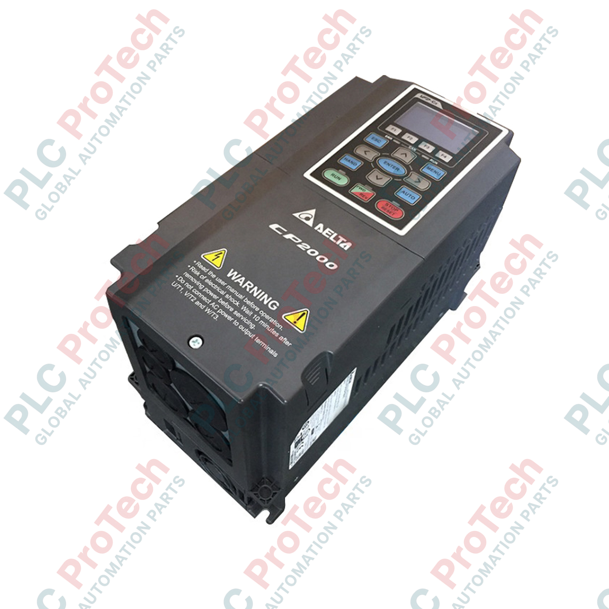
Providing precise speed and torque regulation for high-capacity induction motors, the Delta Electronics VFD550CP23-00 serves as a robust 3-phase motor control platform for heavy-duty industrial environments. Engineered for fan, pump, and HVAC applications, this 55 kW (75 HP) Variable Frequency Drive utilizes sensorless vector control (SVC) to deliver optimal torque performance under variable load conditions. The device features an integrated 10k-step PLC for decentralized logic control, a built-in MODBUS interface, and a dual-rating design that allows operators to easily transition between normal and heavy-duty operation profiles depending on application demands.
Features
-
Advanced Control Modes: Supports Sensorless Vector Control (SVC), V/f control, and FOC+PG for highly precise motor shaft regulation.
-
Embedded Logic: Built-in 10k-step Delta PLC capacity enables local sequence execution without requiring an external controller.
-
Energy-Saving Technology: Dynamic energy-saving algorithms automatically optimize output voltage based on load conditions to minimize operational costs.
-
Modular Hardware Architecture: Hot-swappable LCD keypad and expandable I/O and communication card slots simplify on-site system integration.
-
Integrated Protection: Multi-layer defense circuits protect against overcurrent, overvoltage, undervoltage, phase loss, overheating, and motor overload.
Applications
- Centrifugal fan systems and heavy industrial air handling units (AHUs).
- Municipal wastewater pumping networks and constant-pressure water supply systems.
- Chiller units, cooling towers, and industrial refrigeration compressors.
- Bulk conveyor lines and material handling machinery requiring high startup torque.
Technical Specifications
| Parameter |
Value |
| Manufacturer |
Delta Electronics |
| Model / SKU |
VFD550CP23-00 |
| Series |
VFD-CP2000 |
| Rated Input Voltage |
230V AC (3-Phase, 200V to 240V range) |
| Applicable Motor Capacity |
55 kW / 75 HP |
| Rated Output Current |
110 A |
| Rated Output Capacity |
88 kVA |
| Output Frequency Range |
0.1 to 600 Hz |
| Protection Rating |
IP00 / UL Open Type |
| Physical Weight |
37.6 kg |
| Shipping Weight (Calculated) |
40.0 kg |
| Package Dimensions (Calculated) |
650 mm x 420 mm x 380 mm |
| Country of Origin |
Taiwan |
Connections and Interfaces
| Terminal Block / Pin |
Function / Circuit Assignment |
| R/L1, S/L2, T/L3 |
3-Phase AC Line Input Connections |
| U/T1, V/T2, W/T3 |
3-Phase Variable AC Output to Motor |
| +1, +2 |
DC Bus Reactor Connection (remove jumper before installation) |
| +2, - |
DC Bus Terminals for Brake Unit Connection |
| MI1 to MI8 |
Multi-Function Digital Inputs (Sink/Source selection) |
| RA, RB, RC |
Multi-Function Relay Output (N.O., N.C., Common) |
| SG+, SG- |
RS-485 Communication Terminals (RJ-45 alignment compatible) |
Alternative Models & Compatibility
The VFD550CP23-00 is a core hardware module within Delta's active CP2000 family. It offers direct software configuration compatibility with legacy VFD-F and VFD-G series drives of equivalent electrical classifications. When swapping older components, confirm physical mounting footprint tolerances and coordinate control card macro configurations to prevent parameter mapping faults during commissioning.
Application Pitfalls & Engineering Notes
Because this unit is constructed as an IP00 / Open Type device, adequate internal panel ventilation is mandatory. Airflow velocity must be maintained at a minimum of 3.5 m/s across the rear cooling fins. High-inertia applications, such as direct-drive fans, can produce large regenerative voltages during braking; ensure the deceleration S-curve parameters (Pr.01-13) are adjusted or an external braking resistor is deployed to prevent persistent DC bus overvoltage (ov) faults.
Commissioning & Wiring Tips
For motor cable distances exceeding 50 meters, the capacitive line-to-ground charging current may trigger premature Ground Fault Protection (GFF) alarms. Under these installation conditions, we highly recommend installing a 3-phase AC line output reactor directly at terminals U, V, and W. Always run low-voltage control and feedback lines inside separate steel conduits separated from motor and mains input cabling by at least 20 cm.
Installation Guidelines
CRITICAL WARNING: Verify that all upstream high-voltage AC feeders are completely isolated and locked out before initiating terminal connections. Wait at least 10 minutes following source de-energization for internal DC bus capacitors to bleed down below 36V DC. Measure voltage across terminals +2 and - using an industry-standard voltmeter to verify a zero-energy state prior to handling bare conductors.
1
Mount the chassis vertically inside an electrical cabinet on a non-flammable backplate, ensuring 150 mm of vertical clearance is maintained above and below the drive frame.
2
Connect the primary system protective ground to the drive's dedicated PE terminal before running input and output phase lines.
3
Terminate AC line input supply cables directly to terminals R/L1, S/L2, and T/L3. Connect motor supply cables directly to U/T1, V/T2, and W/T3.
4
Ground control wire shields at the drive frame earth location only to suppress electrical noise and avoid damaging ground loop paths.