Description
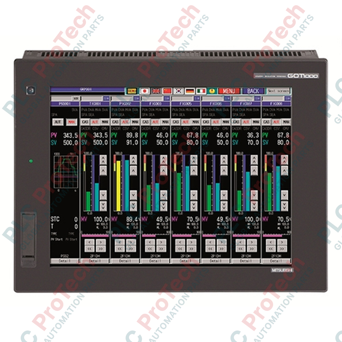
Direct machine-level visualization and multi-channel system control are processed efficiently by the Mitsubishi Electric GT1665M-STBD, a high-performance graphical operator terminal belonging to the GOT1000 platform. Engineered for demanding industrial environments, this unit features an 8.4-inch TFT color display that provides high-contrast, high-resolution diagnostics and control layouts. Equipped with extensive built-in serial, Ethernet, and USB connectivity, it integrates with various factory automation systems, PLC networks, and variable speed drives.
Features
- High-density 8.4-inch SVGA TFT display supporting up to 65,536 colors for clear graphics and text presentation.
- Generous 15 MB flash project memory capacity for storing complex screen configurations, extensive alarm logs, and trend data.
- Comprehensive onboard communication interfaces, eliminating the immediate need for optional expansion cards.
- Robust front panel protection rated to IP67F, ensuring resistance against liquid splashes, oils, and particulate ingress when correctly panel mounted.
- Analog resistive touch screen allowing precise operator inputs and versatile button positioning across the screen surface.
Applications
-
Automotive Assembly Lines: Real-time monitoring of robotic cells, conveyor rates, and pneumatic system status.
-
Packaging and Labeling Systems: Detailed control over parameter settings, recipe management, and high-speed throughput monitoring.
-
Water and Wastewater Treatment: Centralized interface for pump station sequencing, level sensors, and remote telemetry nodes.
-
Chemical Processing Plants: Local control panel operation within environments requiring robust chemical and ingress protection on the control cabinet surface.
Technical Specifications
| Parameter |
Specification Value |
| Manufacturer |
Mitsubishi Electric |
| Model Number |
GT1665M-STBD |
| Display Technology |
TFT Color LCD |
| Screen Dimensions |
8.4 inches (21.3 cm) diagonal |
| Resolution |
800 x 600 Pixels (SVGA) |
| Display Colors |
65,536 Colors |
| Rated Input Voltage |
24V DC (+25%, -20%) |
| Power Consumption |
11.6 W or less (Backlight off: 7.2 W or less) |
| User Memory Capacity |
15 MB (Built-in Flash memory) |
| Front Protection Panel |
IP67F (When panel-mounted) |
| Rear Protection Case |
IP20 |
| Ambient Operating Temperature |
0 to 50 degC |
| External Dimensions (W x H x D) |
241 mm x 190 mm x 52 mm |
| Panel Cutout Dimensions (W x H) |
227 mm x 176 mm |
| Country of Origin |
Japan |
| Shipping Weight (Calculated) |
2.3 kg |
| Package Dimensions (Calculated) |
320 mm x 260 mm x 130 mm |
Connections and Interfaces
| Port / Interface |
Physical Standard |
Functional Description |
| Ethernet Port |
RJ-45 (10BASE-T/100BASE-TX) |
High-speed connection to network PLCs, industrial controllers, and network computer hosts. |
| RS-232 Channel |
D-sub 9-pin (Male) |
Serial connection for logic controllers, barcode scanners, and legacy industrial peripherals. |
| RS-422/485 Channel |
D-sub 9-pin (Female) |
Multi-drop serial link for long-distance connectivity to variable frequency drives and auxiliary controllers. |
| USB Host |
USB-A (USB 2.0) |
Data storage transfer, system backup, and external barcode reader connection. |
| USB Device |
USB Mini-B (USB 2.0) |
Direct PC programming and software uploading/downloading via GT Designer3. |
| CF Card Slot |
CompactFlash Card Type I |
Allows logging of process parameters, runtime alarms, and screen transfer storage. |
Empirical Engineering Insights
Alternative Models & Compatibility
The GT1665M-STBD is a direct successor to legacy GT15 model variations. Projects engineered on GT Designer2 or early versions of GT Designer3 migrate directly to this unit with minor adjustments to resolution and hardware definitions. Users transitioning from older AC-powered HMI units must take extra care to verify that the power distribution on site has been run through a regulated 24V DC system, as this DC model will sustain damage if wired to high-voltage mains lines.
Application Pitfalls & Engineering Notes
When deploying the screen inside heavy chemical, CNC machining, or oil-mist environments, ensure that the front panel's IP67F oil-resistant rubber packing is clean and properly seated during panel cutout insertion. Failure of this seal can cause oil or chemical mist to seep inside the frame, causing touch matrix deterioration or circuit board short circuits. For applications exposed to constant direct sunlight, use a protective sheet to block UV-induced degradation of the resistive overlay.
Commissioning & Wiring Tips
For noise suppression on multi-drop RS-485 configurations, connect the terminal shield wire directly to the functional ground (FG) terminal on the GOT's power connector block. Grounding must be independent; do not daisy chain the ground loop to VFDs or heavy induction motors, as noise injection can induce touch screen instability or drop serial communications entirely.
Installation Guidelines
CRITICAL SAFETY WARNING
Before beginning physical panel cutout preparation or system wiring, isolate all electrical power systems in the target control panel. Discharge static before touching the internal rear board. Verify that the auxiliary 24V DC supply has been shut down and lock-out/tag-out (LOTO) procedures are fully executed.
1
Prepare Panel Cutout: Trace and execute a clean 227 mm x 176 mm cutout within the steel or enclosure faceplate. Ensure all metal filings, burrs, and dust are cleaned up to prevent damage to the gasket.
2
Seat Gasket & Insert GOT: Inspect the rear waterproof packing gasket on the GT1665M-STBD for proper seating. Insert the unit straight into the cutout, taking care not to pinch the rubber edge.
3
Secure Panel Mounting Brackets: Screw the mounting brackets into the dedicated slots along the side chassis of the terminal. Torque the screws to a nominal range of 0.36 to 0.48 N.m to ensure a tight dustproof fit without cracking the bezel.
4
Wire DC Supply and Ground: Securely route 24V DC supply lines to the power terminal block. Ground the unit directly to the control cabinet's primary functional ground point (FG) with a short copper wire rated to at least 2 square millimeters.