Description
Interfacing directly with the system backplane, the ProSoft MV156-MCMR operates as a highly integrated Modbus Master/Slave communication interface module. This module enables serial communication with various industrial control devices, functioning as either a Master or a Slave across independent serial ports. Designed to optimize bandwidth in distributed control networks, the ProSoft MV156-MCMR implements a reduced data block transfer structure, which is ideal for remote I/O configurations or networks with constrained throughput. The module natively manages data transfers, floating-point math scaling, and error checking directly within its onboard processing unit, minimizing processing overhead on the host controller.
Key Features
-
Dual Independent Serial Ports: Each port is configurable as a Modbus Master or Slave, supporting RS-232, RS-422, or RS-485 physical layer interfaces.
-
Reduced Block Transfer: Optimized for remote racks or lower-bandwidth communication links by using smaller block transfer configurations.
-
Comprehensive Protocol Modes: Full compatibility with Modbus RTU (binary with CRC-16) and Modbus ASCII (with LRC error checking) transmission modes.
-
Specialized Floating-Point Integration: Configurable support for specialized floating-point data parsing, including Enron, Daniel, and standard IEEE formats.
-
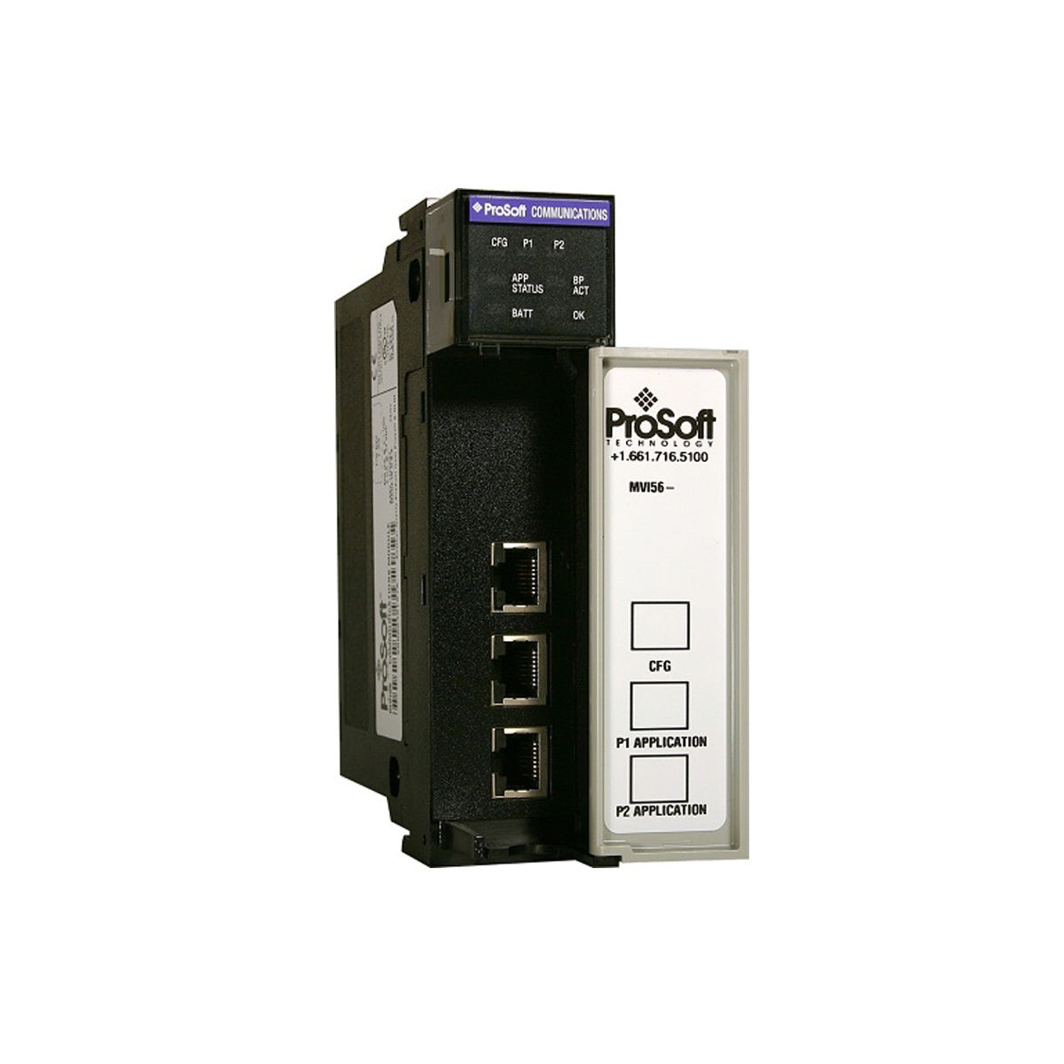
Real-Time Diagnostics: Dynamic visual feedback via front-facing LEDs tracking backplane data transfer, serial port activity, and module health.
Typical Applications
- SCADA and Human-Machine Interface (HMI) coordination across distant terminal sites.
- Integration of flow computers, power monitors, and gas chromatographs in petro-chemical installations.
- Distributed Variable Frequency Drive (VFD) and motor protection relay tracking in MCC panels.
- Building automation and sub-metering infrastructure aggregation.
Technical Specifications
| Specification Parameter |
Value / Details |
| Manufacturer |
ProSoft Technology |
| Model Number |
MV156-MCMR |
| Backplane Current Draw |
800 mA at 5 Vdc, 3 mA at 24 Vdc |
| Operating Temperature |
0 to 60 degC (32 to 140 degF) |
| Storage Temperature |
-40 to 85 degC (-40 to 185 degF) |
| Relative Humidity |
5% to 95% (non-condensing) |
| Vibrational Rating |
5 g from 10 Hz to 150 Hz |
| Operational Shock |
30 g operational, 50 g non-operational |
| Supported Baud Rates |
110 to 115,200 baud |
| Data Bits |
7 or 8 bits |
| Parity Selection |
None, Odd, Even |
| Stop Bits |
1 or 2 |
| RTS Timing Delays |
0 to 65535 milliseconds |
| Shipping Weight (Calculated) |
1.5 kg (3.3 lbs) |
Alternative Models & Compatibility
The MV156-MCMR is functionally optimized to replace standard high-block-size modules in architectures where backplane memory bandwidth is highly constrained. While the traditional MVI56-MCM uses larger transfer blocks, the MCMR variant relies on a reduced, adjustable block design to fit tight network frames. Ensure that the configuration blocks mapped in your ladder logic block layout are adjusted to match the MCMR block sizes to prevent processing faults during system retrofits.
Application Pitfalls & Engineering Notes
When operating at high baud rates (e.g., 115,200 baud) or under heavy packet loading, thermal dissipation within enclosed control panels must be addressed. Ensure adjacent slots provide sufficient passive convection. Additionally, when using Enron/Daniel floating-point modes, verification of the byte-swapping order is necessary to prevent data truncation or alignment mismatches between the controller memory structure and the external field device.
Commissioning & Wiring Tips
For RS-485 daisy-chained communication loops, a termination resistor (120-ohm) must be connected across the TX/RX+ and TX/RX- terminals of the physical end-of-line units. To mitigate electromagnetic interference and shield noise issues, the communication cable shield must be grounded at exactly one physical location in the network loop—preferably at the controller rack termination point.
Installation Guidelines
CRITICAL WARNING:
Isolate and completely shut down all electrical power to the system chassis before inserting, adjusting, or extracting the communication module. Performing hot-swapping or handling live components risks severe physical backplane damage, electrical shock, and communication failures on the remaining active nodes.
1
Turn off all power feeding the system chassis and associated communication field networks.
2
Align the module carefully with the slot guide rails, keeping it perpendicular to the chassis backplane.
3
Firmly slide the module forward until it seats completely into the backplane connectors, then tighten the retaining screws to lock it into position.
4
Connect the serial terminal blocks, power on the chassis, and check the front-panel status LEDs for normal initialization.