Mô tả
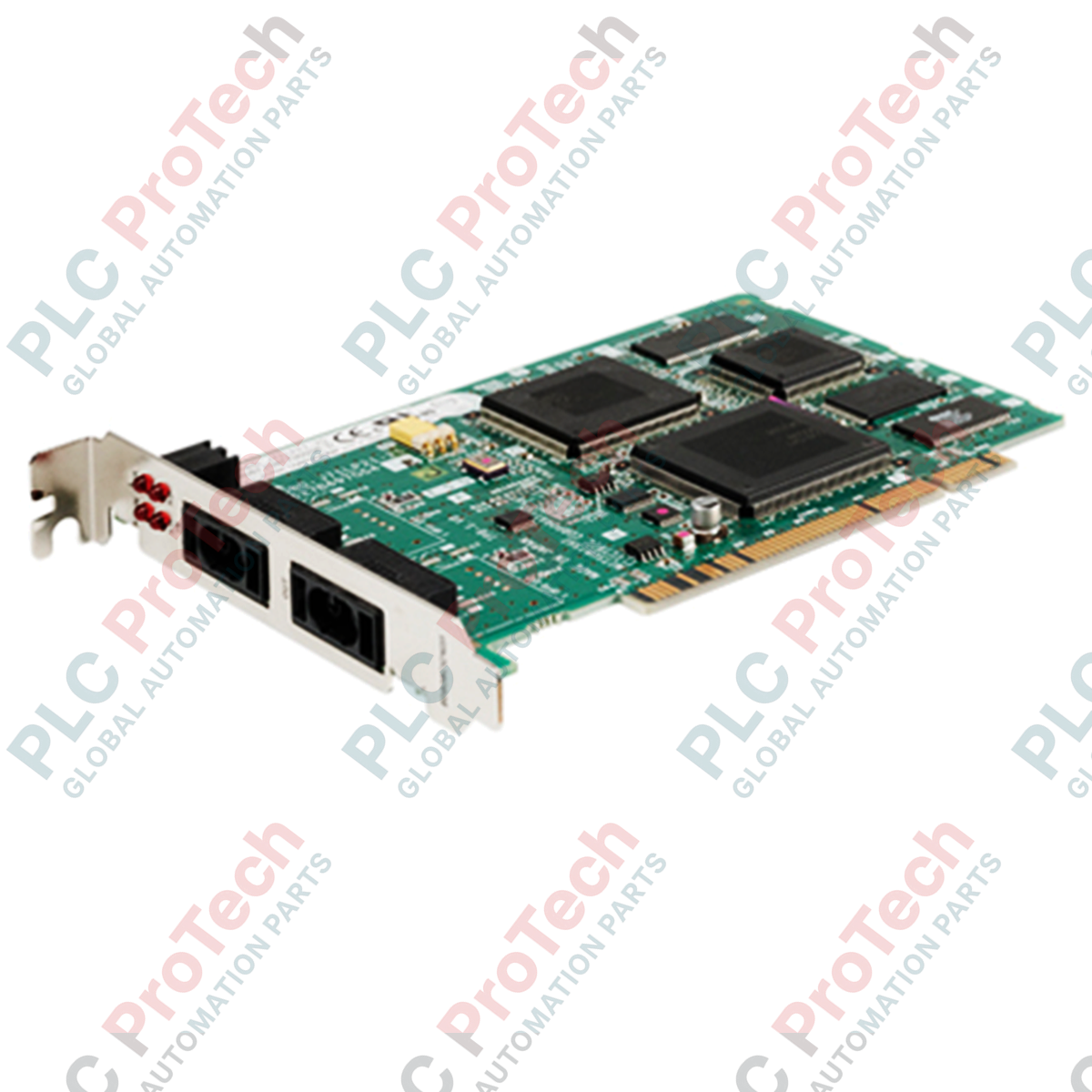
Tích hợp trực tiếp các PC công nghiệp vào các mạng điều khiển tốc độ cao, xác định thời gian, Mitsubishi Electric Q80BD-J71LP21-25 là bo mạch giao diện mạng vòng lặp quang chuyên dụng, được thiết kế để lắp vào các khe mở rộng PCI nửa kích thước. Card giao diện này hỗ trợ trao đổi dữ liệu thời gian thực liền mạch giữa máy tính chủ và mạng PLC MELSECNET/H hoặc MELSECNET/10 cũ, cung cấp khả năng truyền thông cáp quang vòng lặp kép đáng tin cậy. Với tốc độ lên đến 25 Mbps, sản phẩm hỗ trợ truyền tuần hoàn dung lượng lớn và truyền tức thời, đảm bảo các hệ thống giám sát nhận được dữ liệu hiện trường độ phân giải cao với độ trễ tối thiểu.
Tính năng chính
-
Dự phòng vòng lặp kép: Sử dụng cấu trúc liên kết vòng lặp kép với chức năng tự động thực hiện vòng lặp ngược nhằm duy trì tính toàn vẹn của mạng khi một sợi quang bị đứt.
-
Truyền thông tốc độ cao: Có thể lựa chọn tốc độ truyền 25 Mbps hoặc 10 Mbps để phù hợp với các phân đoạn mạng cũ hoặc hiệu suất cao.
-
Nhiều điểm liên kết: Hỗ trợ tối đa 8.192 điểm Rơ-le liên kết (LX/LY) và tối đa 16.384 điểm Thanh ghi liên kết (LW) để xử lý các kiến trúc hệ thống điều khiển phức tạp.
-
Hỗ trợ khoảng cách linh hoạt: Đạt khoảng cách giữa các trạm lên đến 1 km khi sử dụng cáp quang băng thông rộng H-PCF hoặc QSI.
-
Kiểu dáng tiêu chuẩn: Được thiết kế dưới dạng bo mạch PCI nửa kích thước, chiếm một khe duy nhất bên trong các vỏ PC công nghiệp tiêu chuẩn.
Ứng dụng
- Kết nối PC SCADA chính và giao diện người-máy (HMI) với mạng sàn nhà máy.
- Ghi nhật ký dữ liệu mật độ cao, hệ thống điều hành sản xuất (MES) và tích hợp phân tích.
- Giám sát hạ tầng dự phòng tại các cơ sở xử lý nước, năng lượng và lắp ráp ô tô.
- Kết nối các hệ thống PLC dòng Q Mitsubishi phân tán với các nút máy chủ công nghiệp.
Thông số kỹ thuật
| Tham số |
Giá trị |
| Nhà sản xuất |
Mitsubishi Electric |
| Mã model |
Q80BD-J71LP21-25 |
| Loại mạng |
MELSECNET/H (Vòng lặp quang), tương thích với MELSECNET/10 |
| Tốc độ truyền |
25 Mbps / 10 Mbps (có thể lựa chọn) |
| Loại khe giao diện |
Khe PCI (nửa kích thước), chiếm 1 khe |
| Số trạm kết nối tối đa |
64 trạm (1 trạm quản lý, tối đa 63 trạm thông thường) |
| Loại đầu nối cáp quang |
Đầu nối quang song công (tương đương F06 / F08, tuân thủ JIS C 5975/5977) |
| Dòng điện tiêu thụ bên trong (5 VDC) |
0.46 A |
| Nhiệt độ môi trường vận hành |
0 đến 55 độ C |
| Nhiệt độ môi trường bảo quản |
-25 đến 75 độ C |
| Khả năng chịu rung |
Tuân thủ JIS B 3502, IEC 61131-2 |
| Khả năng chịu va đập |
147 m/s2 (gấp 3 lần theo các hướng X, Y, Z) |
| Khối lượng bo mạch tịnh |
0.10 kg |
| Khối lượng vận chuyển (đã tính) |
1.0 kg |
| Nước xuất xứ |
Nhật Bản |
Kết nối và giao diện
| Cổng kết nối |
Chức năng / Phân công |
| Cổng IN |
Nhận dữ liệu quang từ nút mạng trước đó (cáp quang RX) |
| Cổng OUT |
Truyền dữ liệu quang đến nút mạng tiếp theo (cáp quang TX) |
| Cạnh PCI mạ vàng |
Giao diện bus PCI 32 bit tiêu chuẩn để máy tính chủ giao tiếp và cấp nguồn 5VDC |
Thông tin chuyên môn thực nghiệm
Mẫu thay thế & Khả năng tương thích
Q80BD-J71LP21-25 là bản nâng cấp trực tiếp cho các giải pháp giao tiếp cũ. Khi thực hiện chuyển đổi, hãy đảm bảo các cấu trúc phần mềm được cấu hình cho giao thức MELSECNET/10 cũ được chạy ở chế độ tương thích hoặc ánh xạ chính xác vào không gian thanh ghi mở rộng có trong chế độ mở rộng MELSECNET/H, giúp tăng tổng dung lượng mạng lên 35,840 byte.
Cạm bẫy ứng dụng & Ghi chú kỹ thuật
Một điểm thường gây lỗi trong các hệ thống tích hợp máy tính công nghiệp là sụt áp nguồn trên bus PCI. Bo mạch này chỉ tiêu thụ 0.46 A từ đường nguồn 5V của bo mạch chủ. Nếu bảng nối phía sau hoặc bộ nguồn bị sụt áp khi tải xử lý cao, bo mạch có thể đột ngột mất kết nối hoặc các thanh ghi trạng thái chẩn đoán bị đặt lại. Luôn kiểm tra bộ nguồn của máy tính công nghiệp chủ duy trì đường 5V ổn định trong phạm vi dung sai +/- 5%.
Mẹo chạy thử & đấu dây
Để đảm bảo hiệu suất tối ưu ở tốc độ 25 Mbps, chiều dài tối đa của tuyến cáp quang giữa các trạm không được vượt quá 200 mét khi sử dụng cáp quang SI tiêu chuẩn. Nếu cần khoảng cách lên đến 1 km, hãy sử dụng cáp quang QSI hoặc H-PCF băng thông cao. Luôn thực hiện kiểm tra loopback vật lý trong quá trình chạy thử bằng một dây nhảy được xác nhận còn tốt để xác định vấn đề cấu hình bắt nguồn từ thiết lập bo mạch PC cục bộ hay vòng mạng cáp quang bên ngoài.
Hướng dẫn lắp đặt
CẢNH BÁO QUAN TRỌNG: NGUY CƠ VỀ AN TOÀN VÀ TĨNH ĐIỆN
Bo mạch giao tiếp này chứa các linh kiện rất nhạy cảm với phóng tĩnh điện (ESD). Cô lập hoàn toàn máy tính chủ khỏi lưới điện và xả toàn bộ điện tích điện dung còn dư trước khi mở khung máy. Luôn đeo vòng đeo tay nối đất khi thao tác với bo mạch để ngăn ngừa hư hỏng nghiêm trọng lớp oxit cổng.
1
Tắt máy tính công nghiệp chủ, rút dây nguồn và tháo nắp khung máy bên ngoài để lộ các khe PCI.
2
Xác định một khe PCI 32 bit tương thích, còn trống và có kích thước nửa chiều cao. Tháo tấm che trống tương ứng khỏi khung máy.
3
Căn đầu nối cạnh mạ vàng của bo mạch với khe PCI, ấn mạnh xuống đến khi khớp hoàn toàn, rồi cố định giá đỡ bằng vít giữ.
4
Tháo các nắp chống bụi bảo vệ khỏi các cổng bộ thu phát quang. Kết nối đường cáp quang đầu vào với cổng IN và đường cáp quang đầu ra với cổng OUT, đồng thời kiểm tra các chốt định hướng đã khớp chắc chắn.
5
Đóng khung máy tính, cấp nguồn và khởi chạy phần mềm tiện ích kênh Mitsubishi để cấu hình số trạm và chế độ truyền.