Description
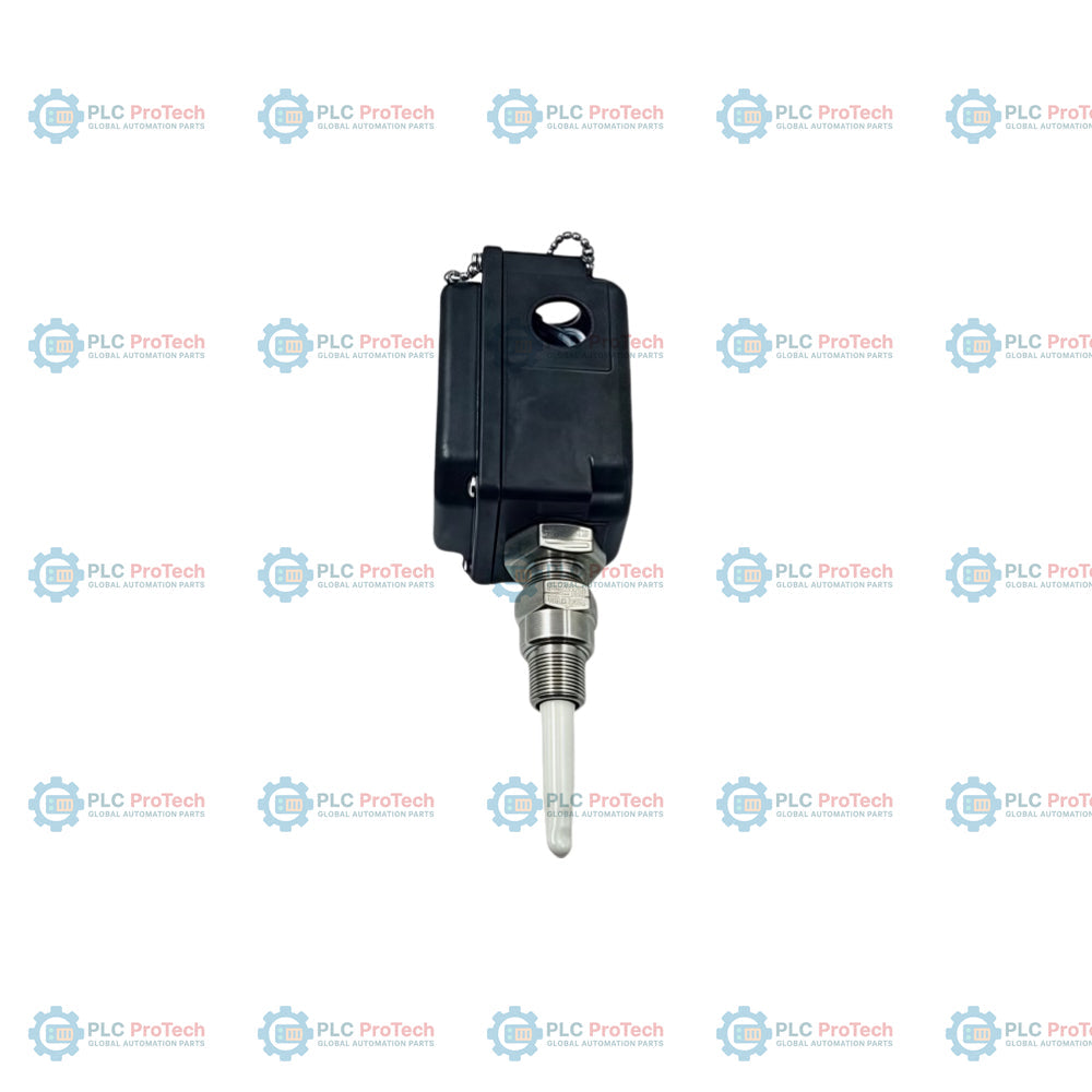
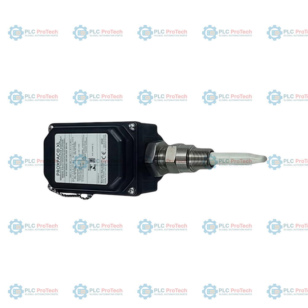
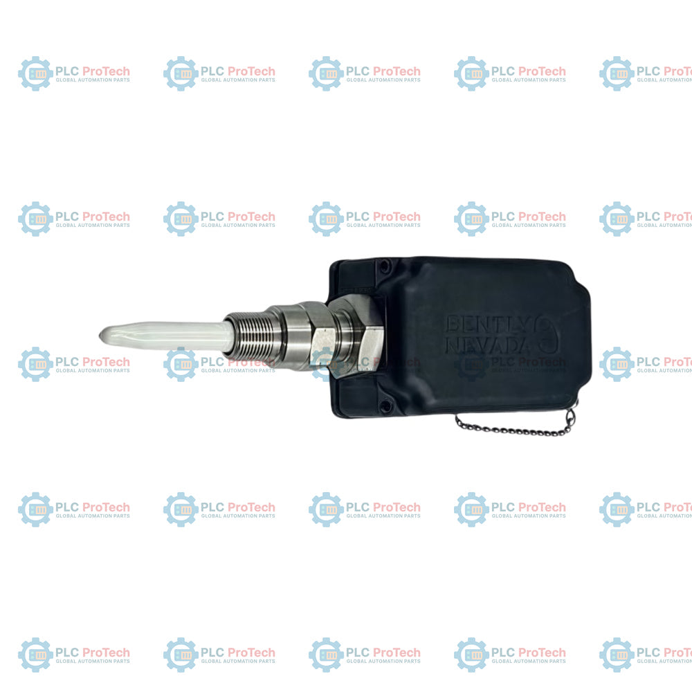
Providing critical non-contact shaft displacement measurements in severe machinery environments, the Bently Nevada 330881-16-00-200-06-02 integrates a specialized proximity probe and electronic assembly inside a highly durable, weather-resistant PROXPAC XL protective enclosure. Designed to bypass the physical vulnerabilities of standard exposed sensors, this assembly shields sensitive coaxial connections from process moisture, corrosive fluids, and physical impacts. It operates as part of the 3300 XL transducer platform, delivering continuous, linear voltage outputs proportional to the distance between the probe tip and the observed target shaft.
Features
-
All-in-One Ruggedized Housing: Combines the proximity probe and connector elements into an environmental junction box designed for aggressive chemical and wet environments.
-
Coaxial Connection Shielding: Internal routing prevents the penetration of water, oils, and particulate matter into critical signal junctions.
-
High-Linearity Output: Provides exceptional accuracy for dynamic vibration and static position monitoring.
-
Broad Compatibility: Interfaceable with Bently Nevada 3500/40M and 3500/42M machinery protection systems.
Applications
- Wet-end rolls, press sections, and dryer zones in paper mills.
- Hydroelectric generator shaft vibration and axial position sensing.
- Cooling tower fan gearboxes and long-span transmission shaft monitoring.
- Wastewater treatment aerators and industrial pumping stations.
Technical Specifications Table
| Parameter |
Value / Specification |
| Manufacturer |
Bently Nevada (Baker Hughes) |
| Model Number |
330881-16-00-200-06-02 |
| Product Line |
PROXPAC XL Proximity Transducer Assembly |
| Output Range |
Typically -2 to -18 Vdc depending on calibration gap |
| Mounting Thread Option |
Standard NPT connection options for rigid conduit deployment |
| Operating Temperature Limit |
-35 to 85 Celsius (standard housing threshold) |
| Country of Origin |
United States |
| Shipping Weight (Calculated) |
2.80 kg / 6.17 lbs |
| Package Dimensions (Calculated) |
300 mm x 300 mm x 200 mm |
Connections and Interfaces
| Terminal / Port |
Signal Assignment |
Description |
| Terminal A / VT |
-24 Vdc Power |
Negative high-stability power input supply from monitor card |
| Terminal B / COM |
Signal Common |
Reference return line to monitoring rack |
| Terminal C / OUT |
Proximitor Signal Output |
Analogue output voltage corresponding to the dynamic gap |
Empirical Engineering Insights
Alternative Models & Compatibility
When replacing older 330800 series PROXPAC models, verify that the existing field conduit entries match the mounting thread layout of the 330881-16-00-200-06-02. This model utilizes modern 3300 XL Proximitor internals, requiring proper configuration of the receiving 3500 series input modules to match its 8V/mm (or 200 mV/mil) scale factor.
Application Pitfalls & Engineering Notes
Moisture accumulation is a common point of failure in washdown environments. If mounting the PROXPAC horizontally or vertically, ensure the conduit connection includes a physical drip loop and a low-point drain seal to prevent water from collecting inside the enclosure over long operating cycles. Thermal stabilization is required before performing final gap measurements; do not perform calibration immediately after starting thermal cycle tests on adjacent gearboxes.
Commissioning & Wiring Tips
To protect against electromagnetic interference (EMI) from high-power variable frequency drives (VFDs) running adjacent machinery, ensure the outer shielding is terminated correctly at the monitor rack common ground only. Grounding the shield at both the PROXPAC enclosure and the rack will introduce ground loops, corrupting the vibration waveforms with 50/60 Hz line harmonics.
Installation Guidelines
CRITICAL WARNING: De-energize all power lines associated with the rack monitor before accessing internal terminal blocks or making field electrical connections inside the PROXPAC enclosure. High static charges on adjacent machinery can cause electric shock or hardware damage. Verify that the installation area is declared non-hazardous before opening standard enclosures.
1
Secure the mechanical installation base to the machine frame, ensuring aligned clearance with the shaft target area.
2
Perform gap calibration by measuring the output voltage on terminals B and C with a digital multimeter until the desired cold-gap target is reached.
3
Tighten all internal coaxial connectors with an appropriate connector wrench to prevent loose contact under high-vibration conditions.
4
Ensure the enclosure cover gasket is fully seated and screw the cover secure to preserve the environmental seal.