Description
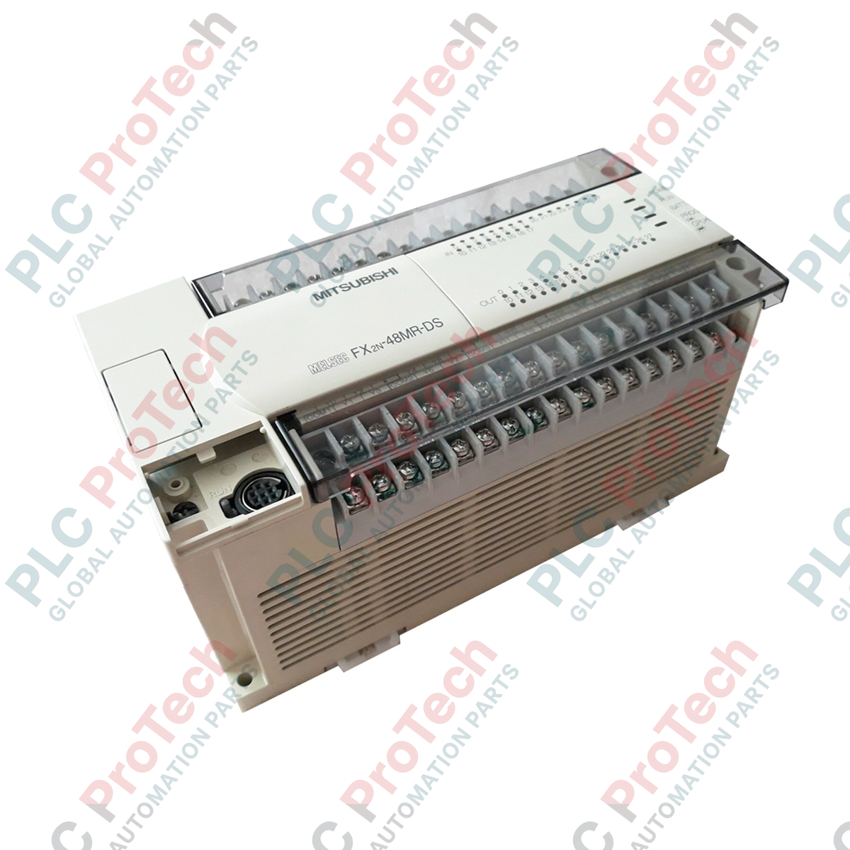
Assembling reliable industrial control architectures requires robust processing cores, and the Mitsubishi Electric FX2N-48MR-DS PLC Base Unit delivers exactly that with its high-density input/output configuration and compact form factor. This controller operates on a 24 VDC power supply, making it an ideal choice for mobile, marine, or battery-backed industrial control systems. It integrates 24 digital inputs and 24 relay outputs within a single chassis, facilitating comprehensive local control without requiring immediate extension modules. Built on the proven MELSEC FX2N architecture, this base unit supports high-speed processing, comprehensive instruction sets, and expandable memory structures to handle mid-range manufacturing and process automation tasks with absolute reliability.
Features
-
24 VDC Power Input: Tailored for standard industrial DC control loops, eliminating the need for AC mains step-down transformers at the controller level.
-
Flexible Input Configuration: 24 digital inputs designed to accept both sink (NPN) and source (PNP) sensor configurations via adjustable terminal wiring.
-
Robust Relay Outputs: 24 electromagnetically isolated relay output channels capable of driving AC or DC actuator loads up to 2A per point.
-
High-Speed Processing: Features integrated high-speed counters and interrupt inputs to accurately track fast-moving industrial pulses.
-
Modular Expandability: Connects seamlessly with FX2N and FX3U expansion blocks, special function modules, and network interfaces for scaling I/O counts.
Applications
- Automated packaging and cartoning equipment operating on 24V bus architectures.
- Conveyor tracking, sorting systems, and specialized material handling machinery.
- Pumping stations, remote telemetry units (RTUs), and localized water treatment plant controls.
- Marine control systems and auxiliary engine monitoring units demanding direct DC power compliance.
Technical Specifications
| Parameter |
Value |
| Manufacturer |
Mitsubishi Electric |
| Model Number |
FX2N-48MR-DS |
| Series |
MELSEC FX2N |
| Supply Voltage |
24 VDC (+20% / -15%) |
| Power Consumption |
30 W |
| Total Integrated I/O |
48 points |
| Digital Inputs |
24 points (24 VDC, Sink/Source selectable) |
| Digital Outputs |
24 points (Relay, 2A/point, 8A/common max) |
| Output Switching Voltage |
Max. 250 VAC, Max. 30 VDC |
| Response Time |
Approx. 10 ms (relay contact mechanical delay) |
| Program Capacity |
8,000 steps (expandable to 16,000 steps with RAM/EEPROM cassettes) |
| Programming Interface |
RS-422 (8-pin Mini-DIN) |
| Ambient Operating Temperature |
0 to 55 degC |
| Country of Origin |
Japan |
| Shipping Weight (Calculated) |
0.85 kg |
| Package Dimensions (Calculated) |
190 x 110 x 100 mm |
Empirical Engineering Insights
Alternative Models & Compatibility
The FX2N series is a legacy workhorse. For modern retrofit configurations where direct replacement stock is limited, the FX3G or FX5U series are suitable functional upgrades. However, note that physical footprint differences and instruction-set updates require code conversion inside GX Works2 or GX Works3. For direct drop-in replacement without modifying the mounting layout, preserving an exact FX2N-48MR-DS unit is critical to avoiding wiring alterations and ensuring compatibility with existing memory cassettes.
Application Pitfalls & Engineering Notes
When switching inductive loads (such as solenoid valves or contactor coils) with the integrated relay outputs, back-EMF spikes can cause contact erosion and premature failure. Always install external RC snubbers across AC loads and flyback diodes across DC loads to protect the internal relays. Additionally, ensure the cabinet's 24 VDC power supply capacity is sized to account for both the 30W PLC draw and the inrush current of all connected field sensors.
Commissioning & Wiring Tips
To configure the digital inputs, locate the "S/S" terminal. Wiring 24V to "S/S" configures the inputs as Sink (NPN type), while wiring 0V to "S/S" configures them as Source (PNP type). To minimize electromagnetic interference on high-speed inputs (X0 through X5), use shielded twisted-pair cables for signal paths and ground the shield only at the PLC chassis grounding terminal.
Installation Guidelines
CRITICAL WARNING
Disconnect all primary power sources before performing any mounting, wiring, or maintenance procedures on the PLC. Verify complete physical de-energization and confirm no residual capacitive charges remain. Failure to isolate power can result in electrical shock, equipment destruction, or erratic machine startup.
1
Mount the controller horizontally onto a standard 35mm DIN rail or directly to the enclosure backplane using the integrated mounting screw holes. Ensure a minimum 50mm clearance on all sides to allow proper convective cooling.
2
Connect the 24 VDC supply power to the dedicated L+ and M terminals on the power supply terminal block. Verify polarity before energizing to prevent input protection fuse failures.
3
Ensure the PLC grounding terminal (Class D grounding, 100 ohms or less resistance) is bonded directly to the main system earth ground point using a heavy-gauge copper conductor.
4
Wire input and output signal lines through the integrated terminal blocks. Keep high-voltage AC lines completely segregated from low-voltage DC signals and communication lines to prevent signal coupling.