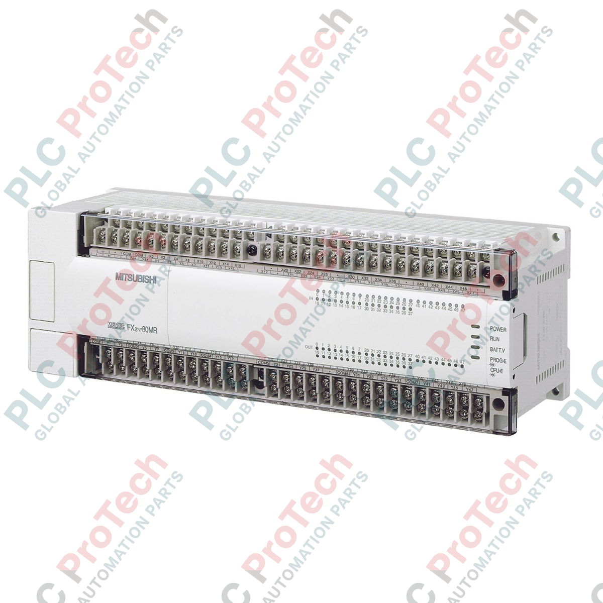
Description
Managing up to 80 physical local I/O points, the Mitsubishi Electric FX2N-80MR-DS serves as a high-speed, DC-powered controller within the legacy FX2N micro-PLC architecture. This base unit integrates processing, memory, and high-density input/output control in a single compact chassis. Operating on a nominal 24V DC power supply, it is engineered for field environments where AC mains are unavailable or where battery-backed power systems are mandatory. The platform features 40 digital inputs and 40 relay outputs, providing robust isolation and high switching capacity for diverse industrial actuators and sensors.
Key Features
-
DC Power Infrastructure: Designed to run directly on 24V DC (+20% / -15% ripple), making it highly suitable for mobile machinery, marine installations, and backup-critical systems.
-
Selectable Input Logic: 40 integrated digital inputs configurable as either sink (NPN) or source (PNP) to match existing field sensor topologies.
-
Robust Relay Outputs: 40 electromagnetic relay outputs capable of switching up to 2A per point for both AC and DC load circuits.
-
Processing and Memory: Built-in 16,000-step RAM and EEPROM program memory capacities for complex industrial control algorithms.
-
High-Speed Inputs: Includes integrated high-speed counter phases (up to 60 kHz single-phase, 20 kHz dual-phase) for direct rotary encoder feedback.
-
Expandable Architecture: Fully compatible with FX2N series expansion blocks, special function modules (analog, temperature, positioning), and communication adapters.
Applications
-
Distributed Pump and Valve Control: Ideal for water purification plants and remote pumping stations using direct-current solar array batteries.
-
Material Handling and Conveyor Systems: Provides high I/O density to manage multiple photoelectric sensors, interlocks, and pneumatic solenoid valves.
-
Mobile Equipment Automation: Deployed on utility vehicles, marine vessels, and heavy transport equipment where the onboard supply is strictly 24V DC.
-
Auxiliary Packaging Machinery: Performs rapid logic control for sealing, cutting, and wrapping stations requiring isolated relay operations.
Technical Specifications Table
| Parameter |
Specification Value |
| Manufacturer |
Mitsubishi Electric |
| Model Reference |
FX2N-80MR-DS |
| Product Series |
MELSEC FX2N Series |
| Operating Voltage |
24V DC (+20% / -15%) |
| Total I/O Points |
80 Points |
| Digital Inputs |
40 Points (24V DC, Sink/Source) |
| Digital Outputs |
40 Points (Relay, isolated) |
| Max. Relay Load Current |
2A per point; 8A per group (4 points); 30V DC / 240V AC max. |
| Program Memory |
16,000 steps (RAM/EEPROM internal or optional cassette) |
| Response Time |
Inputs: approx. 10 ms; Outputs: approx. 10 ms (relay mechanical lag) |
| Internal Current Consumption |
40W (Maximum power consumption) |
| Country of Origin |
Japan |
| Shipping Weight (Calculated) |
1.45 kg |
| Package Dimensions (Calculated) |
310 mm x 115 mm x 110 mm |
Connections and Interfaces
| Terminal Designation |
Function / Connection Specification |
| + / - (Power) |
Primary 24V DC input supply terminals. |
| S / S Terminal |
Input common terminal. Connect to 24V for Sink (NPN) configuration or 0V for Source (PNP) configuration. |
| X000 to X047 |
40 channel digital inputs. X000 to X005 are high-speed counter compatible. |
| COM0 to COM7 |
Common return terminals for isolated relay output groups. |
| Y000 to Y047 |
40 channel physical relay contacts. External circuit fuses should be matched to load groupings. |
Empirical Engineering Insights
Alternative Models & Compatibility
The FX2N-80MR-DS is an older classic micro-PLC architecture. If you are retrofitting or replacing an older FX2-80MR-D, the FX2N model offers equivalent physical spacing but operates with substantially faster processing speeds and a larger instruction library. For modern migrations, note that the FX2N range is superseded by the MELSEC iQ-F (FX5U) series. Upgrading to an FX5U-80MR/DS requires an FX5-CNV-BUS bus conversion module to retain any downstream legacy FX2N expansion units.
Application Pitfalls & Engineering Notes
Relay wear is the most common failure vector for this device in high-duty environments. When driving inductive loads (such as DC solenoid valves or motor contactor coils), you must install an external flyback diode (for DC loads) or an RC snubber circuit (for AC loads) across the load. Failure to do so will cause contact arcing, degrading the internal relays and leading to premature weld-shut failures. Maintain clear ventilation space around the PLC; ambient operating temperatures inside the panel must not exceed 55 degC.
Commissioning & Wiring Tips
Ensure the S/S (Sink/Source) terminal is tied directly to the correct reference voltage before powering the unit. Leaving this floating will result in digital inputs failing to register. If routing encoder lines into X000 through X005, use high-quality twisted pair shielded cabling and terminate the shield at a single point near the panel ground bar to suppress high-frequency EMI.
Installation Guidelines
CRITICAL WARNING: Verify that all 24V DC incoming lines and field-side AC/DC load circuits are fully de-energized prior to terminal connection or chassis installation. Under no circumstances should live terminal blocks be wired. Failure to comply may damage sensitive logic components and cause physical injury.
-
1
Mount the base unit onto a standard 35mm DIN rail horizontally. Ensure the top and bottom ventilation slits are not obstructed by adjacent wiring trunks or metal enclosures.
-
2
Connect a dedicated system ground wire from the Functional Earth (FE) terminal on the PLC to a low-impedance copper ground bus.
-
3
Wire the 24V DC supply lines to the '+' and '-' terminals using cross-sections of at least 1.25 mm2 (AWG 16).
-
4
Double-check your Sink/Source configuration by verifying the link on the S/S terminal before energizing the control cabinet.