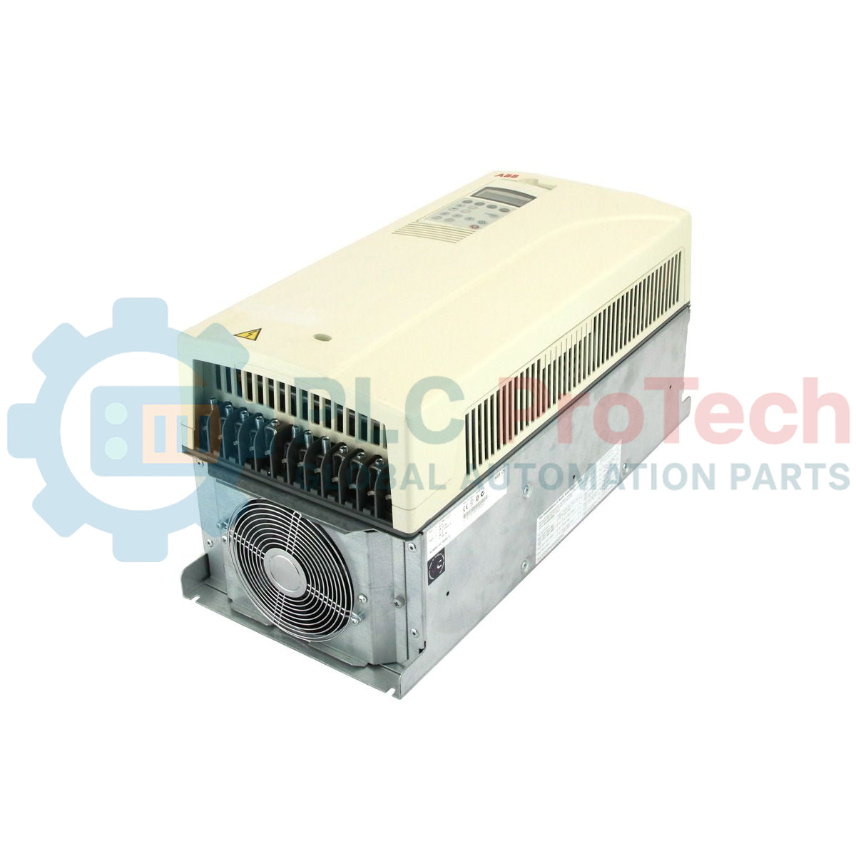
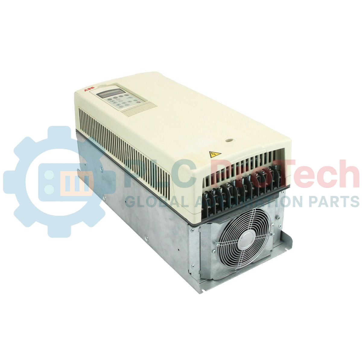
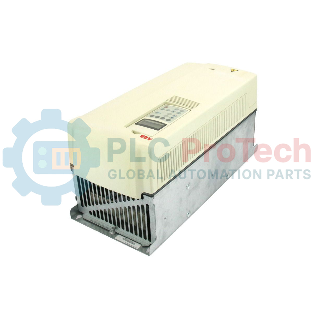
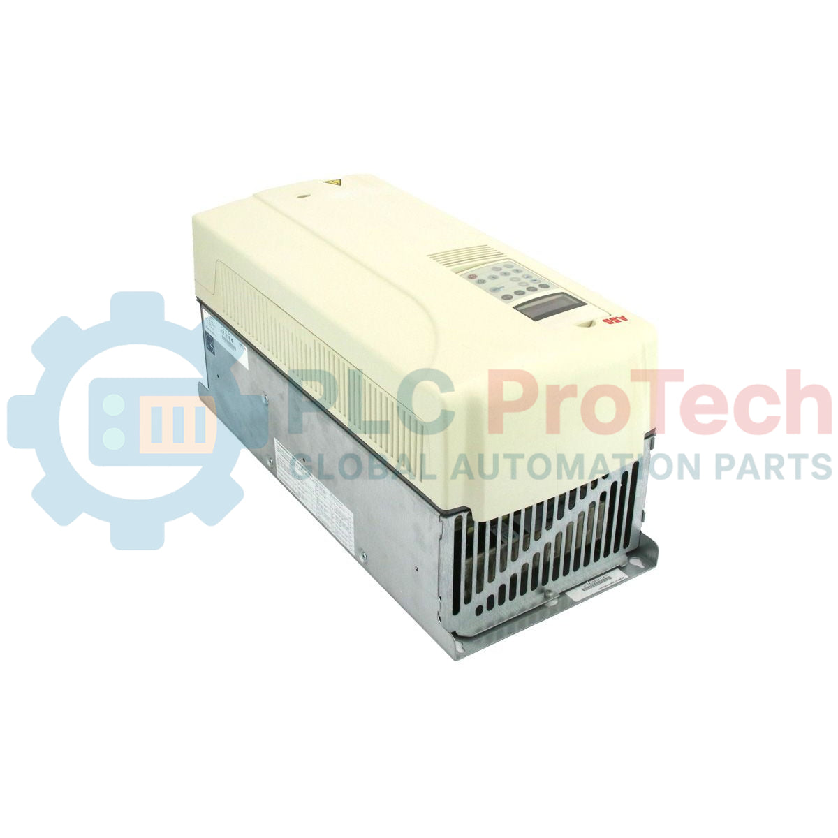
Description
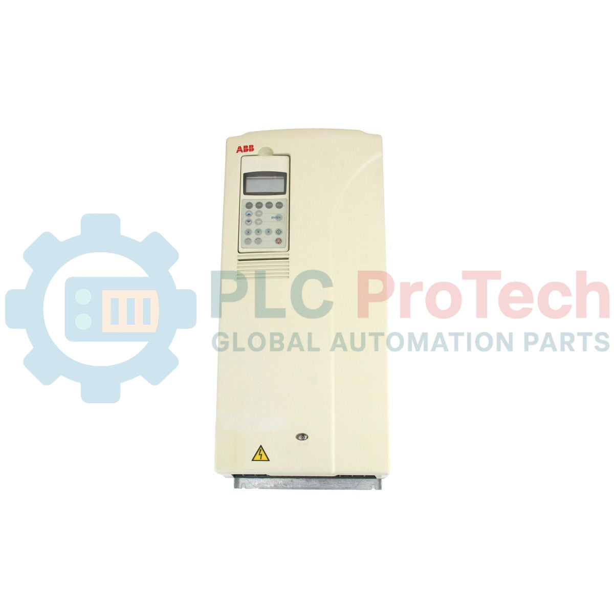
Engineered for precise speed and torque control in heavy-duty industrial applications, the ABB ACS800-01-0050-3 provides reliable motor regulation across variable load profiles. This wall-mounted variable frequency drive features ABB proprietary Direct Torque Control (DTC) technology, enabling high-dynamic accuracy without requiring encoder feedback. Equipped with an integrated AC choke for harmonic mitigation and dynamic braking options, the drive ensures optimal power quality and system protection in demanding environments.
Key Features
-
Direct Torque Control (DTC): Provides premium motor control performance, rapid torque response, and accurate speed regulation.
-
Harmonic Reduction: Features a built-in line reactor (AC choke) to limit input current harmonics and protect internal DC bus components.
-
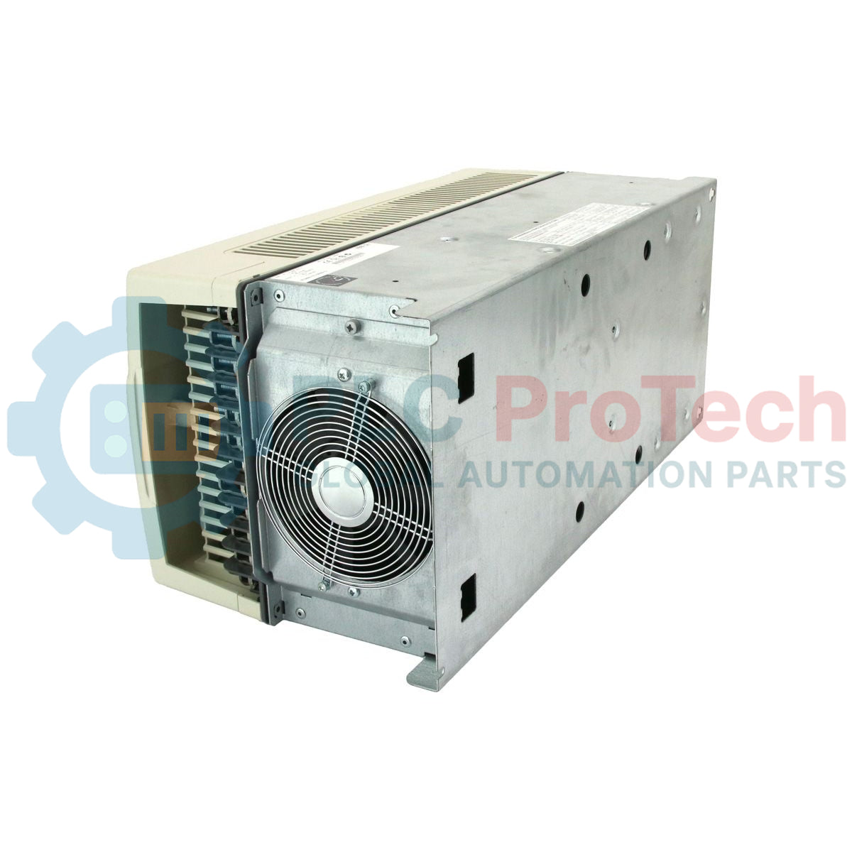
Robust Enclosure Design: Compact Frame R5 wall-mountable chassis rated for standard IP21 protection.
-
Flexible Control Interface: Features the RMIO control board with extensive analog and digital I/O channels.
Applications
-
Centrifugal Pumps and Fans: Optimized flow regulation and energy savings using quadratic load curves.
-
Conveyor and Material Handling Systems: High starting torque capabilities and smooth acceleration/deceleration control.
-
Mixers and Extruders: Precise constant torque delivery at low operating speeds.
Technical Specifications
| Parameter |
Specification |
| Manufacturer |
ABB |
| Model Designation |
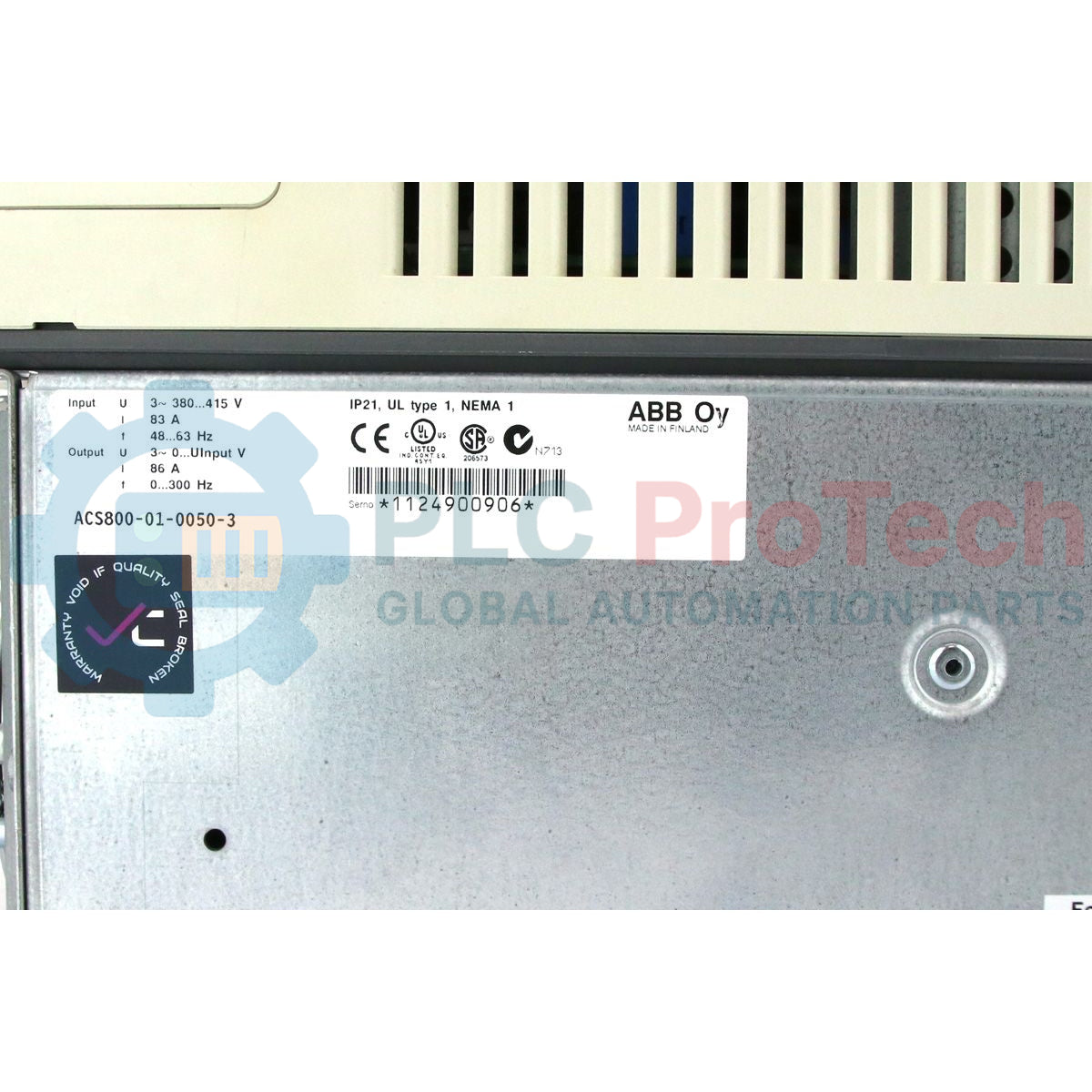
ACS800-01-0050-3 |
| Frame Size |
R5 |
| Input Voltage Range |
380 to 415 V AC (3-Phase) |
| Input Frequency |
48 to 63 Hz |
| Normal Duty Rating (Pn) |
45 kW / 86 A continuous output |
| Light Overload Rating (Pld) |
37 kW / 80 A continuous output |
| Heavy Duty Rating (Phd) |
30 kW / 60 A continuous output |
| Apparent Power Output |
60 kVA |
| Efficiency Class |
IE2 |
| Standby Power Loss |
97 W |
| Operating Temperature Range |
0 to 50 degC (derating applicable above 40 degC) |
| Dimensions (H x W x D) |
739 mm x 265 mm x 286 mm |
| Net Weight |
34 kg |
Connections and Interfaces
| Terminal Block |
Signal / Circuit Assignment |
| U1, V1, W1 |
3-Phase Mains Input Voltage Supply |
| U2, V2, W2 |
3-Phase Output to AC Induction Motor |
| UDC+, UDC- |
Intermediate DC Link Terminals (Dynamic Braking / Common DC Bus) |
| X21 (RMIO) |
Analog Inputs (AI1, AI2) and Programmable Analog Outputs |
| X22 (RMIO) |
Programmable Digital Inputs (DI1 to DI6) and 24 V DC Auxiliary Supply |
| X23, X25, X26 |
Programmable Relay Outputs (RO1, RO2, RO3) for status signaling |
Empirical Engineering Insights
Alternative Models & Compatibility
The ACS800-01 standard wall-mounted drive utilizes the RMIO (Motor Control and I/O) board. When replacing older units, verify the firmware revision loaded on the RMIO card (such as Standard Control Program ASXR7xxx). For systems operating under master-follower configuration or DSU control, the specific firmware parameters must match exactly. While the newer ACS880 series is the general migration path, the ACS800-01-0050-3 continues to be a drop-in replacement, avoiding control network redesigns in systems utilizing older DDCS fiber-optic networks.
Application Pitfalls & Engineering Notes
For Frame Size R5 wall installations, dynamic ventilation is critical. The drive dissipates a significant amount of heat at full output. Ensure at least 200 mm of clear space above and below the cooling fan assembly. If mounting inside an enclosure, verify that the cabinet cooling capacity can offset the internal heat loss. Avoid placing the drive in high-humidity or highly conductive dust environments without adequate secondary containment, as conductive particles can cause immediate short circuits across the DC bus capacitors.
Commissioning & Wiring Tips
During commissioning, performing an ID Run (Identification Run) is vital for Direct Torque Control accuracy. If the application allows, decouple the motor from the load to perform a "Standard ID Run." If uncoupling is impossible, use the "Reduced ID Run" or "ID Run Still" parameters to map the motor stator resistance accurately. Ensure 360-degree grounding of the motor cable shields at the gland plate to suppress high-frequency electromagnetic interference (EMI) that can disrupt sensitive local analog sensors.
Installation Guidelines
CRITICAL WARNING
Before beginning any installation, maintenance, or terminal wiring procedures, isolate the input power supply from the drive. Wait a minimum of 5 minutes after disconnecting the power supply to allow the internal DC bus capacitors to discharge to safe voltage levels. Always verify with a calibrated multimeter that the voltage between UDC+ and UDC- (or UDC+ and frame ground) is below 50 V DC before making contact with terminal connections.
-
1
Mechanical Mounting: Securely mount the R5 frame vertically to a flat, non-flammable wall surface using appropriate M6 heavy-duty bolts.
-
2
Power Cable Routing: Connect the three-phase input mains to terminals U1, V1, and W1. Connect the shielded motor cables to U2, V2, and W2.
-
3
Shielding and Grounding: Ensure a low-impedance ground connection is made between the drive's PE terminal, the motor frame, and the mains distribution board PE.
-
4
Control Wiring & Configuration: Wire necessary digital and analog inputs to the RMIO block. Close the chassis cover, apply input power, and enter motor nameplate data into parameter group 99 to initiate commissioning.