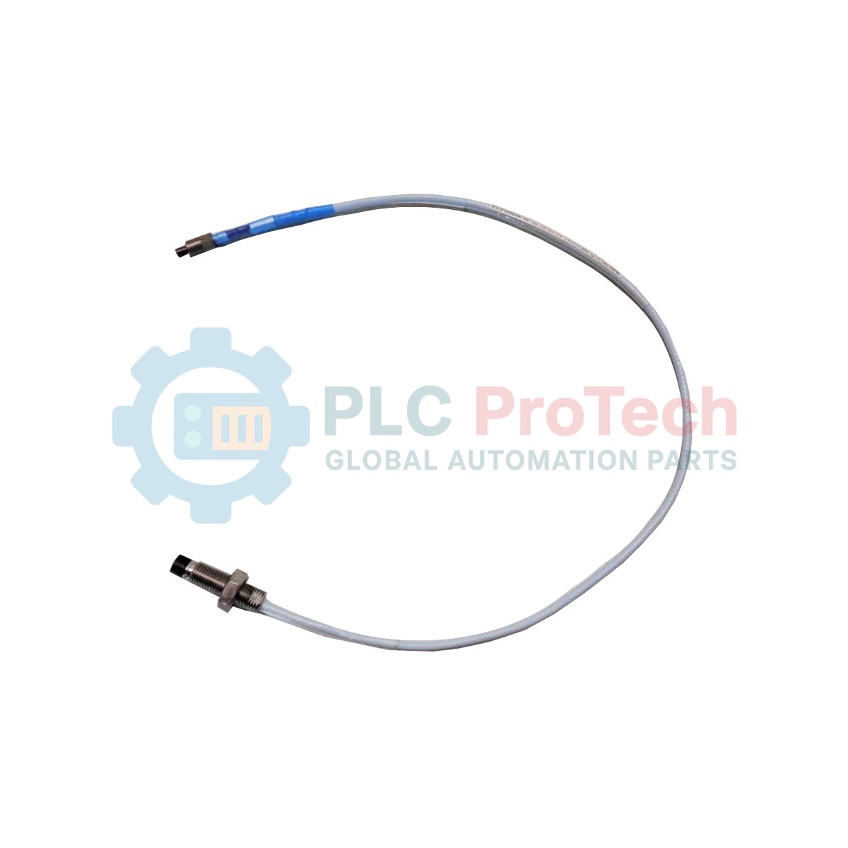
Description
Machinery protection and condition monitoring architectures rely on the Bently Nevada 330101-00-11-20-02-CN to capture precise, non-contact measurements of shaft vibration and position. As a vital component of the 3300 XL 8 mm proximity transducer line, this probe translates physical distance to rotating or reciprocating shafts into continuous electrical feedback. Built to withstand aggressive industrial fluids and thermal stress, the unit operates reliably within critical turbomachinery housings.
Features
-
High-Performance Tip: Crafted from polyphenylene sulfide (PPS) to resist fluid absorption and chemical degradation.
-
Rugged Housing: AISI 303 or 304 stainless steel case shields the internal sensing coil from structural shear.
-
Interlocking Cable Connection: Equipped with a ClickLoc miniature coaxial connector to secure the signal path under high vibration.
-
Coaxial Insulation: FEP-insulated 75-ohm triaxial probe cable limits signal degradation and electromagnetic noise coupling.
Applications
- Turbine shaft dynamic radial vibration monitoring.
- Centrifugal compressor thrust and axial displacement measurement.
- Hydrocarbon pump rotor dynamics and eccentricity analysis.
- High-speed industrial gearbox shaft position monitoring.
Technical Specifications
| Parameter |
Value |
| Manufacturer |
Bently Nevada |
| Model Number |
330101-00-11-20-02-CN |
| Unthreaded Length |
0 mm (Option 00) |
| Overall Case Length |
1.1 inches (Option 11) |
| Total Length |
2.0 meters / 6.6 feet (Option 20) |
| Connector/Cable Type |
Miniature coaxial ClickLoc connector, standard cable (Option 02) |
| Agency Approvals |
Country-specific certifications (CN Option) |
| Probe Tip Material |
Polyphenylene sulfide (PPS) |
| Case Material |
AISI 303 or 304 Stainless Steel (SST) |
| Cable Insulation |
Fluoroethylene propylene (FEP), triaxial |
| Net Weight |
0.323 kg |
| Shipping Weight (Calculated) |
1.500 kg |
| Country of Origin |
United States |
Connections and Interfaces
| Interface Element |
Description & Purpose |
| ClickLoc Coaxial Plug |
Male miniature coaxial terminal designed to couple securely with matching female ClickLoc connectors on extension cables. Prevent hand-tightening past the tactile click to avoid pin damage. |
| Triaxial Cable Shield |
Outer conductor layer that isolates weak high-frequency RF signals from EMI/RFI interference induced by nearby electric machinery. |
Empirical Engineering Insights
Alternative Models & Compatibility
This probe has a physical length of 2.0 meters. In Bently Nevada 3300 XL 8 mm systems, the combined length of the probe and extension cable must match the required electrical length of the Proximitor sensor (either 5.0 meters or 9.0 meters). If utilizing a 5.0-meter Proximitor sensor, a 3.0-meter extension cable must be matched with this 2.0-meter probe. Interchanging mismatching lengths introduces severe scale-factor errors and invalidates sensor calibration.
Application Pitfalls & Engineering Notes
The system calibration is designed around AISI 4140 steel as the target material. Using a different target material (such as stainless steel or aluminum) without recalibrating the Proximitor sensor significantly skews the millivolt-per-mil scale factor. Additionally, ensure adjacent probe tips are separated by a minimum physical distance of 40 mm (1.6 inches) to prevent electromagnetic cross-talk in dual-probe dynamic shaft vibration setups.
Commissioning & Wiring Tips
Always clean ClickLoc connectors with electronic contact cleaner before mating to clear trace grease, oils, or dust. Avoid twisting the coaxial cable during the threading process; utilize a split-conduit mounting bracket or twist-free dynamic positioning setups. Secure the locknuts without over-torquing to safeguard the stainless steel thread profile.
Installation Guidelines
CRITICAL WARNING: De-energize and lock out all machinery drive systems and high-voltage power inputs before opening monitoring glands or reaching near active shafts. Ensure matching electrostatic grounds are established to prevent potential discharge in explosive environments.
1
Inspect the physical target area and confirm that target surfaces are free of deep tooling marks, runout, and magnetic fields.
2
Carefully thread the probe housing into the sleeve or mounting plate while ensuring the attached cable rotates freely without twisting.
3
Adjust the gap between the probe tip and target shaft using a dial indicator or monitor DC bias voltage feedback, aiming for the linear operating region (typically -10 VDC).
4
Tighten locknuts to secure the physical adjustment and push the ClickLoc coaxial connection together until a physical detent click is felt. Wrap the junction in silicone connector sleeves.