Description
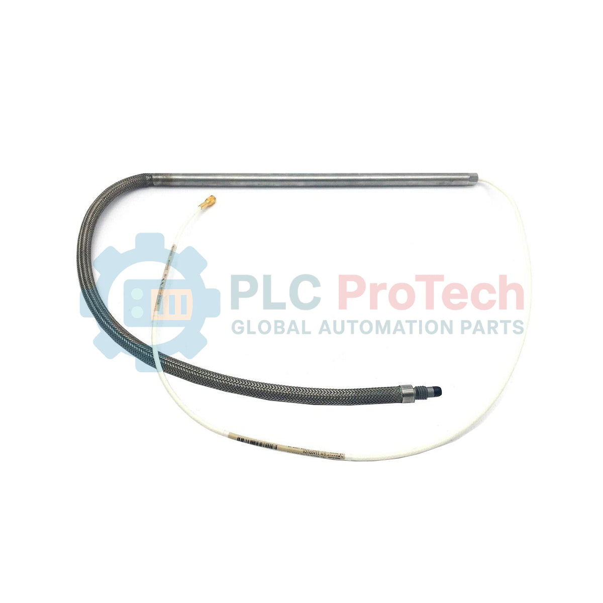
Engineered for high-reliability machinery protection systems, the Bently Nevada 86691-01780-1300-15-00 delivers precise non-contacting dynamic displacement and vibration measurements in critical rotating machinery. This high-precision proximity probe utilizes eddy current technology to continuously monitor shaft position, radial vibration, and axial thrust. Designed to interface seamlessly with standard industrial machinery protection systems, it translates physical distance changes into an analog voltage signal proportional to the gap, allowing operations teams to prevent catastrophic mechanical failures.
Key Technical Features
-
Eddy Current Sensing Principle: Enables friction-free, non-contact measurement unaffected by oil, water, or steam in the target environment.
-
Robust Mechanical Design: Engineered to withstand harsh industrial environments, including high temperatures and corrosive chemical exposure.
-
Precision Suffix Configuration: The 86691-01780-1300-15-00 specific configuration parameters ensure exact mechanical and electrical alignment with targeted machine casings.
-
System Compatibility: Operates reliably with designated Bently Nevada proximitor sensors and monitoring racks.
Industrial Applications
- Steam and gas turbine shaft vibration monitoring.
- Centrifugal and axial compressor axial displacement tracking.
- High-pressure boiler feed pump rotor dynamics observation.
- Gearbox input and output shaft misalignment detection.
Technical Specifications
| Manufacturer |
Bently Nevada |
| Model Number |
86691-01780-1300-15-00 |
| Product Type |
Proximity Probe Assembly |
| Measurement Technology |
Eddy Current (Non-contacting) |
| Base Part Number |
86691 |
| Unthreaded / Case Length Code |
-01780 |
| Cable Length Code |
-1300 |
| Connector Option |
-15 |
| Agency Approval Option |
-00 |
| Country of Origin |
United States (USA) |
| Shipping Weight (Calculated) |
2.0 kg |
Empirical Engineering Insights
Alternative Models & Compatibility
This probe must be matched with its designated proximity transducer (Proximitor) loop. Ensure the total electrical length of the probe and extension cable matches the calibration of the Proximitor (typically 5-meter or 9-meter system calibrations). Mixing unmatched cable lengths will distort the scale factor (e.g., standard 7.87 V/mm or 200 mV/mil) and introduce significant measurement errors into the TSI (Turbine Supervisory Instrumentation) system.
Application Pitfalls & Engineering Notes
Cross-talk can occur if multiple proximity probes are mounted too close to one another without adequate physical separation. Maintain a minimum distance of at least three probe tip diameters between adjacent probes to prevent electromagnetic interference between the high-frequency RF carrier signals. Additionally, target material changes (non-4140 steel) modify the magnetic permeability, requiring specific factory or field recalibration.
Commissioning & Wiring Tips
When routing the probe cable, always isolate it from high-voltage motor feeds or transient control lines to avoid noise injection. Use dedicated, grounded metal conduit or tray systems. The coaxial connection between the probe cable and extension cable must be clean, dry, and protected using self-amalgamating tape or dedicated connector protectors to avoid impedance changes due to fluid intrusion.
Field Installation Guidelines
CRITICAL FIELD WARNING:
De-energize all connected monitoring systems before starting installation. Do not perform probe adjustment or wiring changes while the machinery protection system is active to prevent false trips of critical machinery. Avoid over-tightening the casing nuts, as excessive torque will permanently damage the internal coaxial structure.
1
Verify Target Gap: Position the probe in the mounting bracket and adjust its physical distance relative to the target shaft. Use a precision micrometer or monitor the DC voltage output of the Proximitor to ensure the gap falls within the linear range.
2
Secure Threaded Locknuts: Once the target gap voltage is set (typically around -10 VDC for mid-range calibration on 200 mV/mil systems), tighten the locknuts to the recommended torque spec to prevent drifting under operational vibration.
3
Conduit Connection: Route the probe lead-in cable through a protective flexible conduit, ensuring it is not subjected to sharp bends or tension. Check that the minimum bend radius is strictly observed.