Description
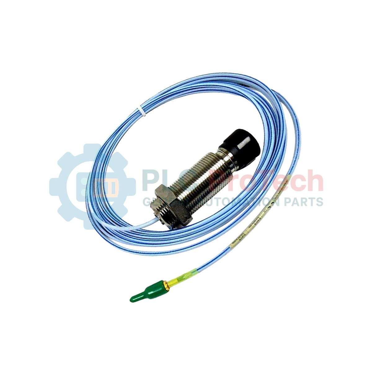
Engineered for demanding turbomachinery protection environments, the Bently Nevada 330851-02-000-050-90-00-CN proximity probe delivers highly stable non-contact static and dynamic displacement measurements. This sensor is a core constituent of the 3300 XL 25 mm Proximity Transducer System, specifically configured to monitor thrust displacement, differential expansion, and shaft position in utility-class steam turbines, gas turbines, and heavy industrial compressors.
Features
-
Extended Linear Range: Specifically calibrated for large-displacement parameters where standard 8 mm probes lack sufficient measurement span.
-
Robust Mechanical Design: M30x2 metric threaded stainless steel case offering structural resistance to high-torque field installation.
-
Unarmored Routing Configuration: Equipped with a 9.0-meter coaxial cable optimized for protective conduit layouts.
-
Hermetic Integration: The 25 mm tip structure features oil and chemical resistance, safeguarding the internal coil from harsh turbine-well fluids.
-
Target Compatibility: Calibrated as standard for high-accuracy tracking on AISI 4140 steel target materials.
Applications
- Thrust position and axial wear monitoring in heavy industrial steam/gas turbines.
- Differential expansion tracking of turbine rotors relative to the machine casing.
- Dynamic radial vibration measurements in heavy-duty utility machinery.
- Reciprocating compressor rod drop and shaft position detection.
Technical Specifications
| Parameter |
Specification Value |
| Manufacturer |
Bently Nevada |
| Model Number |
330851-02-000-050-90-00-CN |
| Product Line |
3300 XL 25 mm Transducer System |
| Probe Tip Diameter |
25 mm |
| Probe Case Type |
M30x2 Metric Thread (Option 02) |
| Unthreaded Length |
0 mm (Option 000) |
| Overall Case Length |
50 mm (Option 050) |
| Total System Length |
9.0 meters / 29.5 feet (Option 90) |
| Cable Armor |
No Armor (Option 00) |
| Agency Approvals |
CN / Country-Specific (China) |
| Country of Origin |
United States (USA) |
| Shipping Weight |
1.30 kg / 2.87 lbs |
Empirical Engineering Insights
Alternative Models & Compatibility
The 330851-02-000-050-90-00-CN 25 mm probe is electrically distinct from standard 8 mm or 5 mm proximity probe systems. This unit must never be connected to 3300 XL 8 mm Proximitor Sensors, as mismatching the probe coil inductance with the incorrect driver will prevent calibration and trigger system error states. This probe is exclusively compatible with 3300 XL 25 mm Proximitor Sensors.
Application Pitfalls & Engineering Notes
Because of the large 25 mm diameter sensor tip, this probe exhibits a larger electromagnetic field footprint compared to smaller probes. To avoid cross-talk or side-wall interference, engineers must maintain a clear radial distance of at least 76 mm (3.0 inches) from any adjacent metallic objects. Standard factory calibration is performed with AISI 4140 steel targets; using other target alloy profiles will result in scale-factor deviation.
Commissioning & Wiring Tips
When routing the unarmored 9.0-meter integrated coaxial cable, ensure the minimum bend radius of 25.4 mm (1.0 inch) is strictly observed to prevent fracturing the inner conductor. To ensure signal integrity at the monitor, protect the miniature coaxial connectors inside a dedicated junction box, and seal all thread junctions with self-coalescing silicone tape to block the entry of moisture and chemical vapors.
Installation Guidelines
CRITICAL WARNING
Before installing or replacing the proximity probe, ensure that the monitoring rack and associated machinery auxiliary systems are fully de-energized. Avoid hitting the probe tip against the observed target during physical installation, as impact can damage the internal coil assembly.
1
Thread the M30x2 probe body into the mounting bracket or sleeve until the probe tip lightly touches the target surface.
2
Back off the probe to establish the target physical gap. Connect the coaxial system to the Proximitor and monitor the DC output voltage to calibrate precisely to the mid-range linear region.
3
Tighten the locknuts to the standard torque requirements, ensuring the probe body remains secure and does not rotate.
4
Route the 9.0-meter coaxial cable through protective metal conduit to the junction box to safeguard the installation from EMI and physical strain.