| Nenn-Eingangsspannung |
120/240 VAC oder 125 VDC |
| Eingangsspannungsbereich (AC Versorgung) |
Betriebsgrenzen 90 bis 264 VAC, 47 bis 63 Hz |
| Eingangsspannungsbereich (DC Versorgung) |
Kontinuierlicher Eingangsspannungsbereich 100 bis 150 VDC |
| Eingangsleistungsaufnahme |
Typisch 135 Watt, maximal 160 Watt Lastbereich |
| Eingangs-Halbwellen-Spitzenstrom |
Typische Dauerstromgrenze 3 Ampere |
| Aktiver Leistungsfaktor |
Aktiver Leistungsfaktor größer als 0,93 bei Volllastbetrieb |
| Ausgangsleistungskapazität |
Maximal 100 Watt Gesamtleistung über alle 3 Ausgangspfade |
| Ausgangsspannung (+5 VDC Schiene) |
4,90 bis 5,25 Volt (5,07 Volt nominale Referenz) |
| Ausgangsspannung (+12 VDC Schiene) |
11,75 bis 12,6 Volt |
| Ausgangsspannung (-12 VDC Schiene) |
-12,6 bis -11,75 Volt |
| Überspannungsgrenze (+5 VDC Ausgang) |
Abschaltfenster 5,7 bis 6,7 Volt |
| Überstromgrenze (+5V Ausgang) |
Typische Schutzschwelle 21 Ampere |
| Überstromgrenze (+12V Ausgang) |
Typische Schutzschwelle 3,5 Ampere |
| Überstromgrenze (-12V Ausgang) |
Typische Schutzschwelle 1,6 Ampere |
| Haltezeitkapazität |
Mindestens 21 Millisekunden Haltezeit ab Verlust des AC-Eingangs |
| Betriebstemperaturbereich |
0 bis 60 Grad Celsius (32 bis 140 Fahrenheit) Umgebungstemperatur |
| Lagertemperaturbereich |
-40 bis +85 Grad Celsius (-40 bis +185 Fahrenheit) Umgebungstemperatur |
| Interne Sicherungsbewertung & Typ |
2 Ampere, 250 Volt Hochleistungssicherungs-Schutz |
| Drehmoment für Klemmenblockschrauben |
12 in-lb (1,3 N-m) |
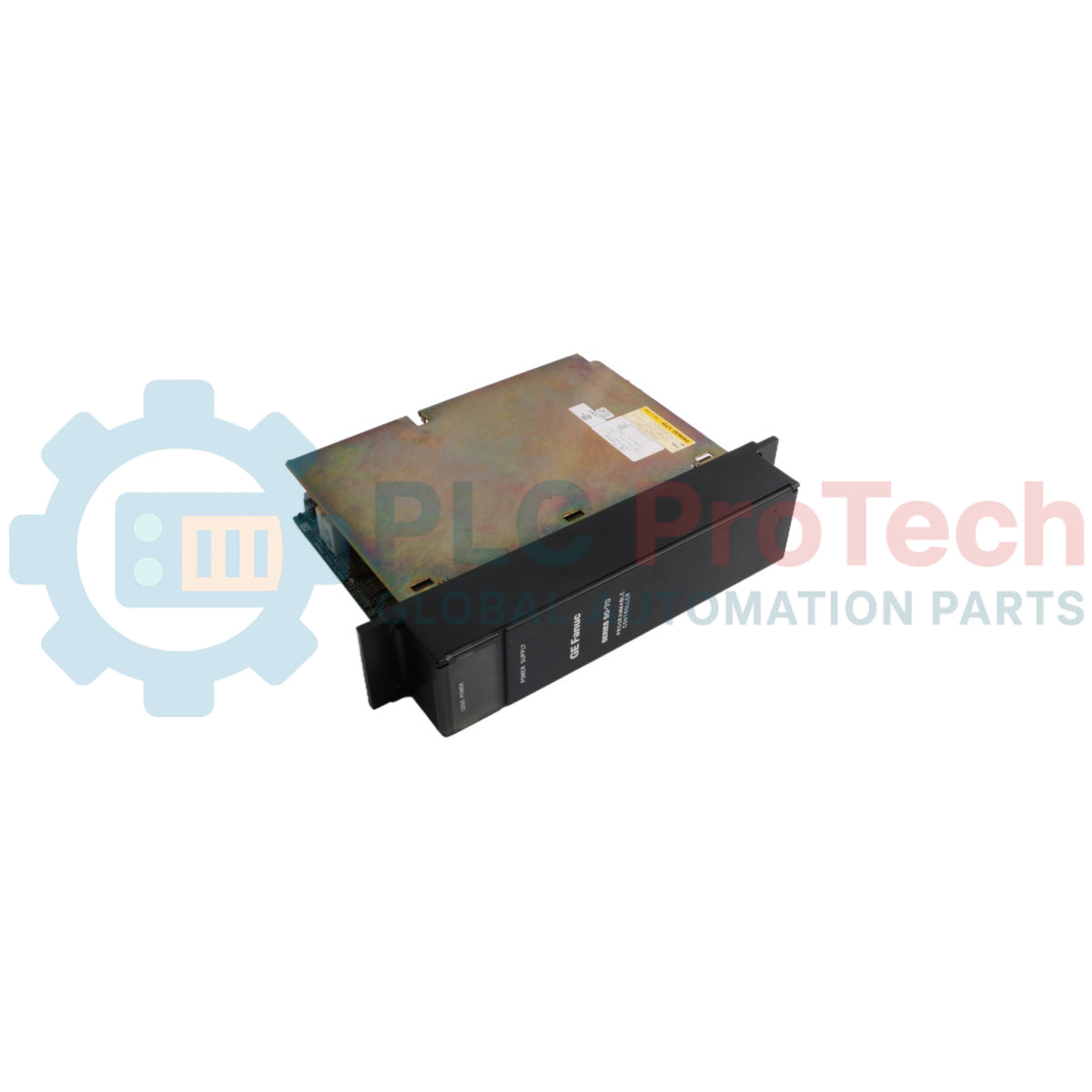
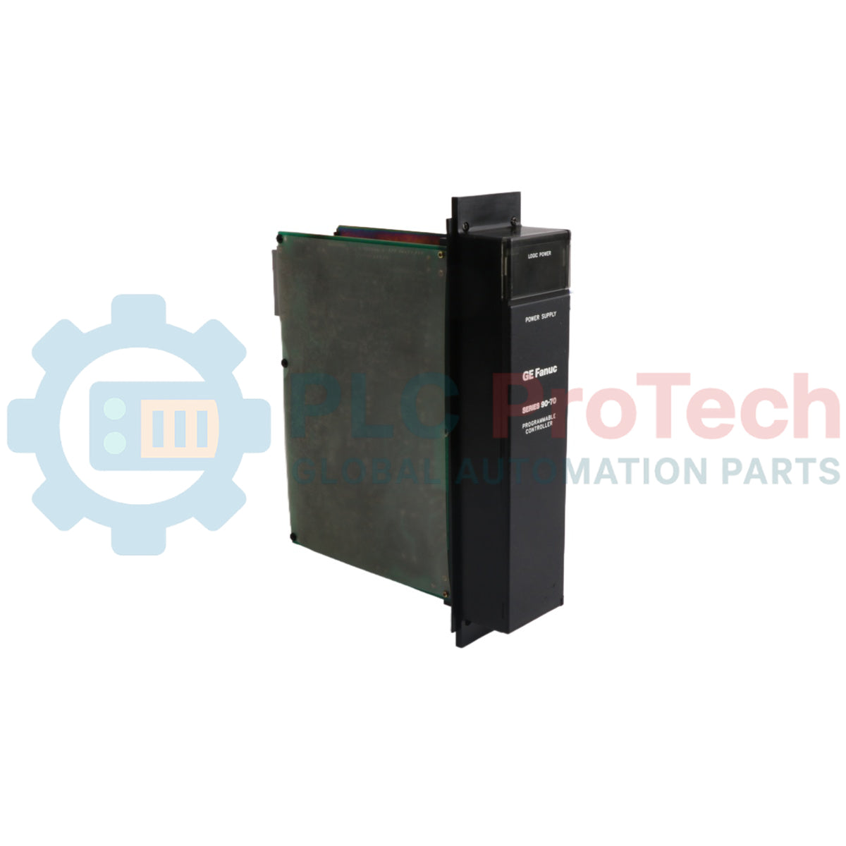
| Hersteller |
GE Fanuc Automation |
| Herkunftsland |
USA |
| Versandgewicht (berechnet) |
1,95 kg |
| Gehäuseabmessungen (berechnet) |
280 mm x 220 mm x 85 mm |