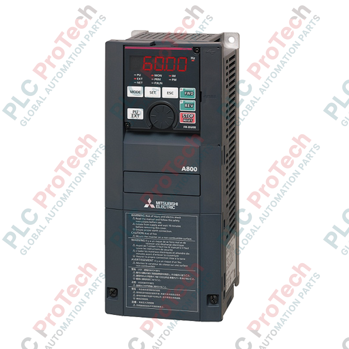
Description
Engineered for high-torque heavy industrial loads, the Mitsubishi Electric FR-A840-3.7K variable frequency drive provides precise vector speed control within the FREQROL-A 800 series portfolio. This high-performance inverter accommodates four distinct duty ratings (SLD, LD, ND, and HD), allowing system integrators to scale motor driving capacity from 2.2 kW up to 5.5 kW based on load profiles. Operating on a three-phase 380 to 500 VAC supply, the FR-A840-3.7K features advanced sensorless vector control, PM sensorless vector control, and built-in RS-485 communications to deliver exceptional speed stability, low-speed torque performance, and seamless automation system integration.
Key Features
-
Four-Class Overload Ratings: Configurable for Super Light Duty (SLD), Light Duty (LD), Normal Duty (ND), and Heavy Duty (HD) profiles to match specific application demands.
-
Advanced Control Algorithms: Supports Real Sensorless Vector Control, PM Sensorless Vector Control, and Vector Control (with optional feedback card) for maximum motor performance.
-
Broad Network Integration: Native RS-485 port with expansion compatibility for CC-Link, CC-Link IE Field, DeviceNet, PROFIBUS-DP, and Modbus RTU.
-
High Starting Torque: Delivers up to 250% starting torque at 0.3 Hz in Heavy Duty (HD) mode under real sensorless vector control.
-
Embedded Safety Functions: Dual-channel safety torque off (STO) compliant with safety standards for protective emergency stop operation.
Applications
-
Conveyor Systems and Material Handling: Utilizing high starting torque and rapid deceleration control.
-
Pumping and Fan Control: Energy optimization using the integrated optimum excitation control algorithm.
-
Extruders and Centrifuges: Heavy-duty speed regulation with continuous load variation recovery.
-
Hoists and Cranes: Precise load positioning utilizing high carrier frequency PWM and mechanical brake sequencing.
Technical Specifications
| Parameter |
Value / Specification |
| Manufacturer |
Mitsubishi Electric |
| Model Number |
FR-A840-3.7K |
| Series |
FREQROL-A 800 |
| Input Voltage / Frequency |
3-phase 380 to 500 VAC, 50 Hz / 60 Hz |
| Allowable Voltage Fluctuation |
323 to 550 VAC, 50 Hz / 60 Hz |
| Normal Duty (ND) Capacity |
3.7 kW (Rated Current: 9.0 A) |
| Super Light Duty (SLD) Capacity |
5.5 kW (Rated Current: 12.6 A) |
| Heavy Duty (HD) Capacity |
2.2 kW (Rated Current: 6.0 A) |
| Output Voltage Range |
3-phase 380 to 500 VAC |
| Output Frequency Range |
0.2 to 590 Hz (Vector/Sensorless limit: 400 Hz) |
| Overload Current Rating (ND) |
150% for 60 seconds, 200% for 3 seconds (at 50 degC) |
| Cooling Method |
Forced Air Cooling |
| Enclosure Protection Rating |
IP20 (Closed type) |
| Operating Temperature |
-10 to +50 degC (LD/ND/HD without freezing); -10 to +40 degC (SLD) |
| Storage Temperature |
-20 to +65 degC |
| Net Mass |
3.3 kg (7.28 lbs) |
| Shipping Weight |
4.4 kg (9.70 lbs) |
Connections and Interfaces
| Terminal Designation |
Signal Type / Assignment |
Electrical Specification |
| R/L1, S/L2, T/L3 |
AC Power Input |
3-phase 380 to 500 VAC, 50/60 Hz |
| U, V, W |
Motor Output Connections |
3-phase modulated variable AC |
| Terminal 2 |
Analog Voltage Frequency Command Input |
0 to 5 VDC, 0 to 10 VDC (Selectable) |
| Terminal 4 |
Analog Current Frequency Command Input |
4 to 20 mA (or 0 to 20 mA) |
| Terminal 1 |
Auxiliary Analog Input (Frequency Offset) |
-10 to +10 VDC or -5 to +5 VDC |
| 12 Control Terminals |
Configurable Contact Inputs (Multi-speed, Reset, STO) |
24 VDC opto-isolated logic |
Empirical Engineering Insights
Alternative Models & Compatibility
The FR-A840-3.7K serves as a direct technical successor to legacy FR-A740-3.7K models. It maintains matching physical mounting patterns, but boasts improved vector algorithm execution. When upgrading a system, parameters from older drives can be extracted and loaded into the newer inverter using Mitsubishi FR Configurator2 software via the integrated USB host port, though phase monitoring characteristics should be verified to prevent minor tuning anomalies on high-inertia loads.
Application Pitfalls & Engineering Notes
Engineers must exercise caution when operating in the Super Light Duty (SLD) rating class. While SLD elevates continuous output current capacity to 12.6 A for variable torque loads (pumps and fans), the permissible operating ambient temperature drops to 40 degC maximum (compared to 50 degC for standard ND and HD configurations). Placing an SLD-configured unit inside an unventilated outdoor panel can lead to rapid thermal de-rating faults (E.THT or E.TBM) if cabinet ambient temperatures surpass 40 degC.
Commissioning & Wiring Tips
Ensure that the hardware slide switches located on the control circuit terminal block are configured to match the intended signal type before applying control voltage. If configuring Terminal 4 for 4 to 20 mA current input, check that Parameter 267 is set to '0' (initial value) and the input selection switch is in the 'I' position. Leaving the switch in 'V' (voltage) while applying a current loop input can damage the analog input circuitry.
Installation Guidelines
CRITICAL WARNING: HIGH VOLTAGE RISK
Before executing any wiring or maintenance operations on this variable frequency drive, isolate the AC primary supply and wait a minimum of 10 minutes. Use a calibrated DC voltmeter to confirm that the DC bus charge LED has extinguished and that voltage across terminal P/+ and N/- has dropped below 30 VDC. Failure to observe discharge times can result in lethal shock or device destruction.
1
Mounting Orientation: Install the inverter vertically on a flat, non-flammable backplate. Ensure at least 50mm of clear spacing above and below the cooling fan exhaust to maintain optimal forced convective airflow.
2
Power and Ground Connections: Terminate phase input lines (L1, L2, L3) and motor output lines (U, V, W) using recommended ring terminals. Ensure the protective earth (PE) grounding terminal is connected directly to the primary panel ground bus bar using a low-impedance copper conductor.
3
Control Shielding: Route all control and analog signal cables through separate wireways, isolated from the high-power input/output cabling. Ground the braided shields of the control lines only at the inverter-end ground plate to eliminate ground loops.