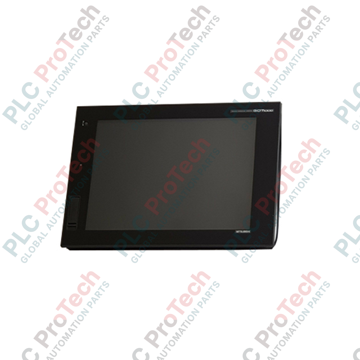
Entwickelt für anspruchsvolle industrielle Visualisierungsaufgaben bietet das GT1695M-XTBD Bediengerät hochauflösendes Monitoring und Steuerung als Teil der Mitsubishi Electric GOT1000 Serie. Dieses leistungsstarke Mensch-Maschine-Interface (HMI) verfügt über ein großzügiges 15-Zoll-TFT-Farbdisplay, das Bedienern klare, Echtzeit-Diagnosedaten und Steuerungsmöglichkeiten direkt auf dem Fabrikboden bereitstellt.
Hauptmerkmale
- Hochauflösendes 15-Zoll-TFT-Display mit XGA (1024 x 768) Auflösung und 65.536 Farben.
- Analoges resistives Touchpanel für flexible Bildschirmgestaltung und präzise Bedienereingaben.
- Multikanal-Kommunikationsmöglichkeiten mit integriertem Ethernet, RS-232 und RS-422/485 Schnittstellen.
- 15 MB interner Flash-Speicher zur Ablage komplexer Projektbildschirme, Betriebssystemdateien und Datenprotokolle.
- Robuster Frontschutz mit Schutzart IP67F gegen Staub, Öl und Wasserspritzer.
- Integrierte USB-Host- und Geräteanschlüsse für einfachen Projekttransfer und Peripherieverbindung.
Anwendungen
- Automobilmontagelinien und Überwachung von Roboterzellen.
- SCADA-Integration für Wasser- und Abwasseranlagen.
- Komplexe Verpackungsmaschinen und Materialflusssysteme.
- Visualisierung von chemischer Verarbeitung und Chargensteuerung.
Technische Spezifikationen
| Parameter |
Spezifikationswert |
| Hersteller |
Mitsubishi Electric |
| Modellnummer |
GT1695M-XTBD |
| Anzeigeart |
TFT-Farb-LCD |
| Bildschirmgröße |
15 Zoll |
| Auflösung |
1024 x 768 Pixel (XGA) |
| Anzeigefarben |
65.536 Farben |
| Eingangsspannung |
24 V DC (+25 %, -20 %) |
| Stromverbrauch |
19 W oder weniger (bei ausgeschalteter Hintergrundbeleuchtung) |
| Interner Speicher |
15 MB Flash-Speicher |
| Schutzart Vorderseite |
IP67F (staubdicht, wasser- und ölbeständig) |
| Schutzart Rückseite |
IP20 |
| Betriebstemperatur |
0 bis 50 °C |
| Herkunftsland |
Japan |
| Abmessungen |
397 mm x 296 mm x 61 mm |
| Versandgewicht (berechnet) |
8,0 kg |
Anschlüsse und Schnittstellen
| Schnittstellenport |
Anschlusstyp & Funktion |
| Ethernet |
RJ-45 (10BASE-T/100BASE-TX) für SPS-Kommunikation und Netzwerküberwachung |
| RS-232 |
D-Sub 9-polig (Stecker) für PC-Anschluss, Barcodeleser oder ältere SPS |
| RS-422/485 |
D-Sub 9-polig (Buchse) für Multi-Drop-PLC-Netzwerke und Steuerverbindungen |
| USB-Host |
USB-A (USB 2.0) für Datenspeicherung, Maus-, Tastatur- oder Druckeranschluss |
| USB-Gerät |
USB Mini-B (USB 2.0) für schnellen Projekt-Upload/Download vom PC |
| Speicherkartensteckplatz |
CF-Karten-Schnittstelle für externe Sicherung, Protokollierung und Betriebssystem-Updates |
Empirische technische Erkenntnisse
Alternative Modelle & Kompatibilität
Das GT1695M-XTBD kann ältere 15-Zoll-Modelle der GT15-Serie (wie die GT1595-Serie) direkt ersetzen. Projektdateien müssen mit der GT Designer3-Software konvertiert werden. Die Ausschnittmaße des Panels sind identisch, was einen direkten physischen Austausch ohne Änderungen an der Gehäusetür ermöglicht.
Anwendungsfallen & technische Hinweise
Hohe Umgebungstemperaturen in geschlossenen Steuergehäusen können die Hintergrundbeleuchtung erheblich schneller altern lassen. Sorgen Sie für ausreichende Belüftung oder Kühlung des Panels, um die Umgebungstemperatur des HMI unter 50 °C zu halten. Vermeiden Sie die Installation in direktem Sonnenlicht, da UV-Strahlung die resistive Touch-Membran mit der Zeit beschädigen kann.
Inbetriebnahme- & Verkabelungstipps
Bei Verwendung der RS-422/485-Serienschnittstelle über lange Distanzen stellen Sie sicher, dass der passende Abschlusswiderstand über die HMI-Systemeinstellungen aktiviert ist. Führen Sie Kommunikationskabel (Ethernet und Seriell) stets in separaten Leitungen, getrennt von Hochspannungs-Motorantriebskabeln, um elektromagnetische Störungen (EMI) zu vermeiden, die Touchscreen-Eingaben oder Kommunikationsverbindungen beeinträchtigen können.
Installationsrichtlinien
KRITISCHE WARNUNG: ELEKTRISCHE GEFAHR
Schalten Sie alle Stromquellen, die das Bedienfeld versorgen, aus, bevor Sie versuchen, das HMI zu installieren, zu verkabeln oder zu entfernen. Vergewissern Sie sich, dass die 24V DC-Stromversorgung vollständig isoliert ist. Andernfalls kann es zu schweren Stromschlägen, Geräteschäden oder Ausfällen der Kommunikationsschnittstelle kommen.
1
Bereiten Sie den Paneelausschnitt gemäß den offiziellen Abmessungen (383,5 mm x 282,5 mm) vor. Stellen Sie sicher, dass die Montagefläche eben und gratfrei ist, um eine ordnungsgemäße IP67F-Abdichtung zu gewährleisten.
2
Setzen Sie das HMI von vorne in den Ausschnitt des Panels ein und stellen Sie sicher, dass die wasserdichte Dichtung korrekt in ihrer Nut sitzt.
3
Befestigen Sie das HMI mit den mitgelieferten Montagevorrichtungen. Ziehen Sie die Schrauben gleichmäßig mit dem angegebenen Drehmoment (0,36 N-m bis 0,48 N-m) an, um eine Verformung des Panels zu vermeiden.
4
Verbinden Sie den funktionalen Erdungsanschluss (FG) auf der Rückseite des Geräts mit einer dedizierten Klasse-D-Erde (100 Ohm oder weniger) unter Verwendung eines mindestens 2 mm² starken Kabels.