Description
Executing precise process loop control within a unified automation chassis, the Mitsubishi Electric Q62HLC operates as a dedicated two-channel proportional-integral-derivative (PID) controller. This high-speed module interfaces directly with the MELSEC Q Series PLC backplane, eliminating the communication lag typical of external standalone controllers. Capable of handling thermocouple, current, and voltage inputs alongside analog control outputs, the unit provides direct closed-loop feedback processing for demanding industrial thermal, pressure, and flow systems.
Features
-
Dual-Channel Control: Two independent PID loops with dedicated auto-tuning and self-tuning algorithms.
-
Universal Input Architecture: Direct connection for thermocouples (types B, E, J, K, N, R, S, T), micro-voltage, and standard analog current signals.
-
High-Speed Loop Execution: Extremely fast sampling cycle of 25 ms per channel, allowing control over rapid physical process changes.
-
Integrated Analog Outputs: Direct 4-20mA or voltage control outputs to interface cleanly with control valves, actuators, and drives.
-
Native PLC Backplane Integration: Map control loop parameters directly into CPU memory registers without custom communication block configurations.
Applications
- Precision plastic extrusion, thermoforming, and blow-molding temperature regulation.
- Industrial heat-treatment furnaces requiring multi-zone PID cascade control.
- High-speed flow-rate and pressure regulation loops in chemical dosing and water-treatment processes.
- Environmental chamber control with simultaneous heating and cooling loop processing.
Technical Specifications Table
| Parameter |
Specification Value |
| Manufacturer |
Mitsubishi Electric |
| Model Number |
Q62HLC |
| Control Channels |
2 Channels (Independent PID execution) |
| Thermocouple Input Types |
B, E, J, K, N, R, S, T |
| Analog Input Range |
Voltage/Current (Direct sensor configuration) |
| Analog Output Channels |
2 Channels (Current/Voltage control outputs) |
| Sampling Cycle |
25 ms per channel |
| Occupied I/O Points |
16 Points (Assigned on the Q-series PLC bus) |
| Internal Current Consumption |
0.27 A (at 5 VDC backplane bus) |
| External Supply Voltage |
24 VDC (+10% / -15%) |
| Operating Temperature Range |
0 to 55 degC |
| Module Weight |
0.25 kg |
| Shipping Weight (Calculated) |
1.00 kg (Includes protective industrial packaging) |
| Dimensions (Calculated) |
98 mm x 27.4 mm x 90 mm (H x W x D) |
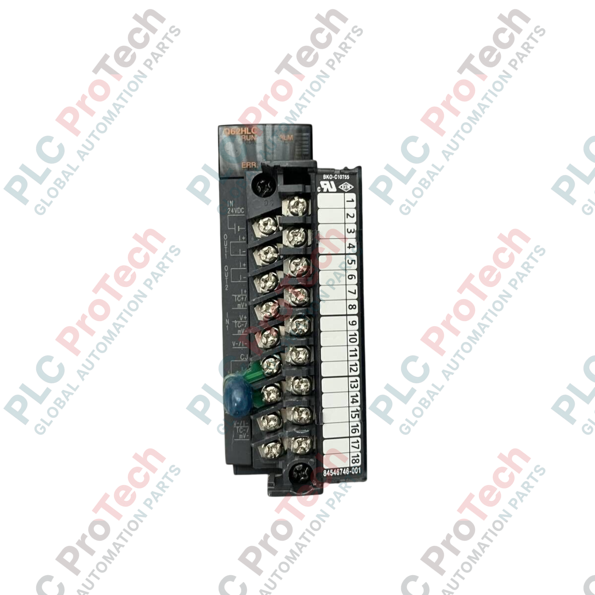
Connections and Interfaces
| Terminal Pin Number |
Terminal Name / Signal Association |
| Terminal 1 |
Channel 1 Temperature / Micro-voltage Input (+) |
| Terminal 2 |
Channel 1 Temperature / Micro-voltage Input (-) |
| Terminal 3 |
Channel 1 Current Input (I+) |
| Terminal 4 |
Channel 1 Control Analog Output (+) |
| Terminal 5 |
Channel 1 Control Analog Output (-) |
| Terminal 10 |
Channel 2 Temperature / Micro-voltage Input (+) |
| Terminal 11 |
Channel 2 Temperature / Micro-voltage Input (-) |
| Terminal 12 |
Channel 2 Current Input (I+) |
| Terminal 13 |
Channel 2 Control Analog Output (+) |
| Terminal 14 |
Channel 2 Control Analog Output (-) |
| Terminal 17 |
External Power Supply Input (24 VDC) |
| Terminal 18 |
External Power Supply Common (0V GND) |
Empirical Engineering Insights
Alternative Models & Compatibility
Unlike the Q64TCRT thermal regulation modules, which execute standard temperature profiling on a slower 500ms cycle, the Q62HLC is a high-speed controller designed for 25ms loop response. It incorporates direct physical analog current/voltage outputs rather than transistor outputs. Consequently, logic written for the Q64 series cannot be directly copied; the buffer memory structure of the module must be re-mapped inside the GX Works software environment.
Application Pitfalls & Engineering Notes
Operating the loop controller on a highly dynamic physical actuator requires careful configuration of the derivative action (D-gain). Due to the rapid 25ms sampling time, high-frequency electrical noise on input terminals can propagate into violent fluctuations in the control outputs. If your control variable exhibits high high-frequency jitter, engage the integrated input filter parameters to stabilize the PID feedback loops before committing to fine-tuning adjustments.
Commissioning & Wiring Tips
The Q62HLC terminal block contains a factory-calibrated Cold Junction Compensation (CJC) resistor mounted directly on the lower terminals. Replacing terminal blocks between modules without matching the calibrated CJC resistor can introduce ambient thermal offsets of several degrees Celsius. Always ensure that the physical terminal block remains paired with its original serial-numbered electronic module to avoid field-drift during startup.
Installation Guidelines
CRITICAL WARNING: Verify that all primary control cabinet power is fully de-energized and lock-out tag-out (LOTO) protocols are active before engaging terminal block connections or inserting the module on the MELSEC Q series base unit. Failure to fully isolate the system can result in immediate physical damage to the module backplane and risk control signal disruption.
1
Insert the bottom mounting hook of the module into the guide notch of the base unit.
2
Pivot the module firmly forward against the base unit to snap the top retention latch in place.
3
Secure the module to the base plate using the top integration screw (torque range 0.36 to 0.48 N-m).
4
Attach external 24 VDC auxiliary power to terminals 17 and 18, and use shielded twisted-pair cables for analog signal paths.