توضیحات
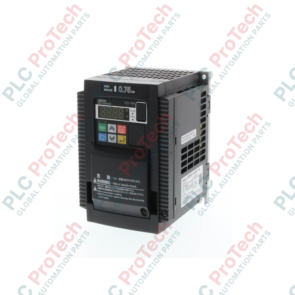
اینورتر چندکاره فشرده با عملکرد بالا امرن 3GEMX2-A4007-ZV1 متعلق به سری MX2 (نسخه کامل ZV1) است. این درایو به طور خاص برای کنترل ماشینآلات با دقت بالا طراحی شده و کنترل پیشرفته توان و سرعت در سرعتهای پایین همراه با ایمنی عملکردی یکپارچه را هماهنگ میکند.
اینورتر با تغذیه سهفاز کلاس 400 ولت کار میکند و برای راهاندازی موتور القایی سهفاز یا موتور همزمان با آهنربای دائم 0.75 کیلووات طراحی شده است. با استفاده از الگوریتم پیشرفته کنترل برداری جریان، گشتاور راهاندازی بالای 200 درصد را در فرکانس پایین 0.5 هرتز به دست میآورد و عملکرد چهار ربع نرم را در شرایط حلقه باز ارائه میدهد. این درایو دارای عملکرد ایمن خاموشی گشتاور (STO) مبتنی بر سختافزار و مطابق با استاندارد ISO 13849-1 (PLd, Cat.3) است که نیاز به کنتاکتورهای ایمنی دوگانه خارجی برای قطع برق موتور را حذف میکند و در نتیجه فضای محفظه و هزینههای منطق کنترل را کاهش میدهد.
ویژگیها
- طراحی با دو رده عملکردی که از حالتهای کار سنگین (CT) و کار سبک (VT) از طریق پیکربندی پارامترها پشتیبانی میکند.
- گشتاور راهاندازی بالا به میزان 200 درصد در فرکانس 0.5 هرتز با کنترل برداری جریان بدون حسگر.
- ورودیهای ایمنی دو کاناله داخلی مطابق با ISO 13849-1 Cat.3 PLd برای عملکرد ایمن خاموشی گشتاور (STO).
- عملکرد ورودی موقعیتیابی ساده و ورودی قطار پالس یکپارچه برای کنترل همزمان سرعت و موقعیت بدون کنترلکنندههای خارجی.
- قابلیت برنامهنویسی درایو داخلی با پشتیبانی از تا 140 خط منطق نردبانی برای وظایف مستقل غیرمتمرکز.
- پورت ارتباطی سریال استاندارد RS-485 با پروتکل Modbus-RTU یکپارچه و پشتیبانی از کارتهای شبکه صنعتی اختیاری.
- سازگاری پیشرفته با موتورهای استاندارد القایی سهفاز و موتورهای همزمان با آهنربای دائم (موتورهای PM).
کاربردها
- خطوط نقاله صنعتی و سیستمهای حمل و نقل لجستیکی
- بالابرهای صنعتی، مکانیزمهای بالابری و جرثقیلهای حمل مواد
- فنهای تهویه گریز از مرکز، پمپهای صنعتی چند مرحلهای و کمپرسورهای هوا
- ماشینهای پیچپیچ، ماشینآلات نساجی و کنترلهای کشش برشدهنده-بازکننده
- محرکهای اصلی ماشینآلات بستهبندی و خطوط تولید فرآوری مواد غذایی
مشخصات فنی
پیکربندی مدل (3GEMX2-A4007-ZV1)
طبق ساختار نامگذاری اینورتر امرن، پارامترهای پیکربندی خاص به شرح زیر رمزگشایی میشوند:
| موقعیت گزینه |
آیتم پیکربندی |
مشخصات فنی |
| مدل |
شناسه سری پایه |
سری فشرده با عملکرد بالا 3GEMX2 / 3G3MX2 |
| محفظه |
کلاس حفاظت محفظه |
A = نوع نصب روی پنل (حداقل IP20) |
| ولتاژ |
کلاس ولتاژ تغذیه ورودی |
4 = کلاس سهفاز 400 ولت AC (از 380 تا 480 ولت) |
| ظرفیت |
حداکثر ظرفیت موتور قابل استفاده |
007 = 0.75 کیلووات (1 اسب بخار) در حالت کار سنگین |
| نسخه |
نسخه نرمافزار/عملکرد |
ZV1 = نسخه استاندارد با برنامهنویسی عملکردی پیشرفته |
الکتریکی
| پارامتر |
مشخصات |
| ولتاژ ورودی نامی |
تغذیه خط AC سهفاز ۳۸۰ تا ۴۸۰ ولت، ۵۰/۶۰ هرتز (نوسان مجاز -۱۵ درصد تا +۱۰ درصد) |
| فاز ورودی |
۳ فاز |
| ظرفیت موتور قابل استفاده |
Heavy Duty (CT): ۰.۷۵ کیلووات / Light Duty (VT): ۱.۱ کیلووات |
| جریان خروجی نامی |
Heavy Duty (CT): ۲.۵ آمپر / Light Duty (VT): ۳.۴ آمپر |
| حداکثر ولتاژ خروجی |
خروجی سهفاز، ۳ سیمه از ۰ ولت تا سطح ولتاژ ورودی تغذیه |
| حداکثر فرکانس خروجی |
۰.۱ تا ۴۰۰ هرتز |
| فرکانس حامل |
۲.۰ تا ۱۵.۰ کیلوهرتز (رتبهبندی پیشفرض Heavy Duty معمولاً در ۳.۰ کیلوهرتز) |
عملکرد کنترل
| پارامتر |
مشخصات |
| روش کنترل |
PWM سینوسی (کنترل V/f، کنترل برداری بدون سنسور) |
| گشتاور شروع |
۲۰۰ درصد در ۰.۵ هرتز هنگام استفاده از کنترل برداری بدون سنسور |
| زمان شتاب/کاهش سرعت |
۰.۰۱ تا ۳۶۰۰.۰۰ ثانیه (پشتیبانی از الگوهای خطی و منحنی S) |
| دقت تنظیم فرکانس |
فرمان دیجیتال: ۰.۰۱ هرتز / فرمان آنالوگ: ۱/۱۰۰۰ فرکانس حداکثر |
محدودههای محیطی
| پارامتر |
مشخصات |
| دمای محیط عملیاتی |
-۱۰ درجه سانتیگراد تا +۵۰ درجه سانتیگراد (در صورت تجاوز دما از مقادیر اسمی نیاز به کاهش ظرفیت است) |
| رطوبت محیط عملیاتی |
۲۰ درصد تا ۹۰ درصد رطوبت نسبی (بدون تراکم و یخزدگی) |
| دمای ذخیرهسازی |
-۲۰ درجه سانتیگراد تا +۶۵ درجه سانتیگراد (شرایط حملونقل کوتاهمدت) |
| ارتفاع نصب |
حداکثر ۱۰۰۰ متر (کاهش ظرفیت اسمی به میزان ۱ درصد به ازای هر ۱۰۰ متر تا ۳۰۰۰ متر) |
| درجه حفاظت بدنه |
IP20 |
مکانیکی
| پارامتر |
مشخصات |
| وزن خالص |
۱.۶ کیلوگرم |
| روش خنکسازی |
خنکسازی اجباری هوا از طریق فن داخلی یکپارچه |
اتصالات / رابطها
ترمینالهای کنترل و تغذیه فرستنده
| گروه ترمینال |
نام ترمینال |
عملکرد |
| مدارهای اصلی برق |
R, S, T |
ترمینالهای ورودی تغذیه خط AC سهفاز |
| مدارهای اصلی برق |
U, V, W |
ترمینالهای خروجی فرکانس متغیر AC سهفاز به موتور |
| مدارهای اصلی برق |
PD, P |
ترمینالهای اتصال چوک لینک DC اختیاری (DCL) (بهصورت پیشفرض جامپر شده) |
| مدارهای اصلی برق |
P, RB |
ترمینالهای اتصال مقاومت ترمز دینامیکی خارجی |
| مدارهای اصلی برق |
G |
ترمینال زمین حفاظتی (PE) |
| ورودیهای کنترل |
1, 2, 3, 4, 5, 6, 7 |
ورودیهای منطق دیجیتال چندمنظوره (قابل تنظیم برای سرعت چندمرحلهای، ریست، جلو/عقب و غیره) |
| ورودیهای کنترل |
P24 |
خروجی مشترک تغذیه کنترل +۲۴ ولت DC (حداکثر جریان ۱۰۰ میلیآمپر) |
| ورودیهای کنترل |
PLC |
ترمینال مشترک برای ورودیهای دیجیتال / ورودی تغذیه منبع خارجی (قابل انتخاب Sink/Source) |
| ورودیهای کنترل |
H, O, OI, L |
ورودیهای آنالوگ (H: مرجع +۱۰ ولت DC، O: ورودی ولتاژ ۰-۱۰ ولت DC، OI: ورودی جریان ۴-۲۰ میلیآمپر، L: مشترک آنالوگ) |
| خروجیهای کنترل |
11, 12 |
خروجیهای دیجیتال کلکتور باز چندمنظوره |
| خروجیهای کنترل |
CM2 |
ترمینال مرجع مشترک خروجی کلکتور باز |
| خروجیهای کنترل |
AM |
ترمینال خروجی مانیتور ولتاژ آنالوگ (۰ تا ۱۰ ولت DC) |
| خروجیهای کنترل |
MA, MB, MC |
خروجی رله چندمنظوره داخلی (MA: معمولاً باز، MB: معمولاً بسته، MC: مشترک رله) |
| رابطهای ایمنی |
GS1, GS2 |
ورودیهای ایمنی مستقل دو کاناله که مستقیماً به مکانیزم قطع خروجی داخلی متصل هستند |
راهنمای نصب
- مسیرکشی و جداسازی کابل: خطوط اصلی برق (خطوط ورودی تغذیه R/S/T و خطوط خروجی موتور U/V/W) باید بهطور دقیق از سیمکشی کنترل یا ارتباطات کمولتاژ جدا شوند و حداقل فاصله موازی ۱۰ سانتیمتر حفظ شود تا از تداخل الکترومغناطیسی جلوگیری شود.
- سایهبان و زمین کردن: موتور را با کابل سهفاز محافظدار پیوسته متصل کنید. لایه محافظ باید اتصال محیطی ۳۶۰ درجه مستقیم به پنل فلزی یا گیره زمین در سمت درایو داشته باشد. ترمینال زمین PE درایو باید به زمین حفاظتی اصلی کارخانه متصل شود.
- فضاهای تهویه محفظه: اینورتر باید به صورت عمودی روی سطح صاف و غیرقابل اشتعال داخل تابلو برق نصب شود. برای حفظ جریان هوای بدون مانع، حداقل فاصله ۱۰۰ میلیمتر در بالا و پایین محفظه درایو و ۵۰ میلیمتر در طرفین چپ و راست باید رعایت شود.
- کاهش EMI/RFI: برای محیطهای حساس به نویز، فیلتر نویز رادیویی سهفاز AC اختصاصی را در سمت ورودی خط درایو نصب کنید و فازهای خروجی موتور را از داخل هسته فریت عبور دهید تا انتشارهای هدایتی و تابشی سرکوب شوند.
- پرشکنندههای اتصال کوتاه ایمنی: درایو با لینکهای اتصال کوتاه نصب شده در کارخانه بین ترمینالهای ورودی ایمنی (GS1، GS2) و سطح منطق مشترک تحویل داده میشود. هنگام اجرای مدار رله ایمنی سختافزاری، این پرشکنندهها باید برای سیمکشی صحیح خط توقف اضطراری برداشته شوند.
انطباق و گواهیها
- CE: گواهی شده تحت دستورالعمل ولتاژ پایین ۲۰۱۴/۳۵/EU و دستورالعمل EMC ۲۰۱۴/۳۰/EU.
- UL/cUL: ثبت شده تحت استانداردهای تجهیزات کنترل صنعتی UL 508C و CSA C22.2 شماره ۱۴.
- ایمنی عملکردی: گواهی شده طبق ISO 13849-1:2006 دسته ۳ PLd و IEC 61508 SIL2.
- RoHS: مطابق با محدودیتهای استاندارد مواد خطرناک.
سؤالات متداول
سؤال ۱: تفاوت اصلی پیکربندی بین حالتهای Heavy Duty (CT) و Light Duty (VT) برای مدل 3GEMX2-A4007-ZV1 چیست؟
پاسخ ۱: در حالت Heavy Duty (CT)، اینورتر تا موتور ۰.۷۵ کیلووات با ظرفیت اضافه بار ۱۵۰ درصد برای ۶۰ ثانیه را پشتیبانی میکند. در حالت Light Duty (VT)، جریان خروجی نامی افزایش یافته تا موتور ۱.۱ کیلووات را پشتیبانی کند اما ظرفیت اضافه بار به ۱۲۰ درصد برای ۶۰ ثانیه کاهش مییابد که برای فنها یا پمپهای با گشتاور متغیر مناسب است.
سؤال ۲: آیا این اینورتر میتواند موتور آهنربای دائم را راهاندازی کند یا فقط محدود به موتورهای القایی استاندارد است؟
پاسخ ۲: فریمور سری ZV1 قابلیتهای کنترل موتور سنکرون با آهنربای دائم (موتور PM) را همراه با الگوریتمهای استاندارد موتور القایی سهفاز AC ادغام میکند و امکان کنترل سرعت و گشتاور حلقه باز برای موتورهای صرفهجویی انرژی سنکرون را فراهم میسازد.
سؤال ۳: چگونه منطق ورودی دیجیتال را بین سیمکشی SINK و SOURCE تغییر دهم؟
پاسخ ۳: انتخاب منطق با جابجایی کلید کشویی واقع در نزدیکی بلوک ترمینال کنترل یا با تغییر اتصال سیمکشی در بلوک ترمینال مشترک PLC مطابق با رابط منطق خارجی PNP یا NPN دلخواه تغییر میکند.
سؤال ۴: اگر فن خنککننده داخلی با انسداد مکانیکی یا نقص مواجه شود، چه اتفاقی میافتد؟
A4: درایو ناهنجاریهای خنککنندگی را تشخیص داده و کد خطای داخلی تولید میکند که باعث فعال شدن توالی قطع خودکار برای جلوگیری از افزایش حرارت بیش از حد ماژولهای IGBT قدرت میشود.
Q5: آیا 3GEMX2-A4007-ZV1 میتواند به عنوان کنترلکننده منطق مستقل عمل کند؟
A5: بله. از طریق عملکرد برنامهنویسی درایو داخلی، تکنسینها میتوانند تا 140 خط نمودار منطق نردبانی را مستقیماً در CPU اینورتر کامپایل و اجرا کنند تا وظایف ورودی/خروجی محلی را بدون PLC خارجی پردازش کنند.
Q6: حداقل تنظیم فرکانس حامل چقدر است و چگونه بر دفع حرارت تأثیر میگذارد؟
A6: فرکانس حامل میتواند بین 2.0 کیلوهرتز تا 15.0 کیلوهرتز تنظیم شود. کاهش فرکانس حامل باعث کاهش تلفات حرارتی در ماژولهای اینورتر میشود اما صدای آکوستیک موتور را افزایش میدهد.
Q7: هدف از رابط ارتباطی Modbus-RTU داخلی چیست؟
A7: پورت RS-485 داخلی اجازه میدهد تا 32 درایو تحت یک کنترلر اصلی شبکه شوند تا پارامترها را تنظیم، کنترل و وضعیتها را با استفاده از ساختارهای استاندارد فریم Modbus خوانده و مدیریت کنند.
Q8: آیا این درایو جمعوجور به ترانزیستورهای ترمز دینامیکی خارجی نیاز دارد؟
A8: خیر. درایو A4007 شامل ترانزیستور ترمز داخلی یکپارچه است. مقاومتهای ترمز دینامیکی میتوانند مستقیماً بین ترمینالهای P و RB متصل شوند بدون نیاز به واحد ترمز خارجی جداگانه.
Q9: پاسخ عملیاتی سیستم ایمنی عملکردی داخلی چگونه است؟
A9: قطع انرژی هر یک از ترمینالهای GS1 یا GS2 باعث میشود مدار درایو گیت داخلی به سرعت توان را از IGBTهای خروجی جدا کند. این توقف غیرکنترلی معادل توقف اضطراری دسته 0 طبق استاندارد IEC 60204-1 است.
Q10: نصب در ارتفاع بالا چگونه بر رتبهبندی درایو تأثیر میگذارد؟
A10: در ارتفاعات بالاتر از 1000 متر، هوای رقیقتر باعث کاهش کارایی خنککنندگی همرفتی میشود. جریان خروجی مداوم درایو باید به ازای هر 100 متر افزایش ارتفاع تا 3000 متر، 1 درصد کاهش یابد.
Q11: آیا این اینورتر میتواند از منبع تغذیه تکفاز 230 ولت برای خروجی سهفاز 400 ولت استفاده کند؟
A11: خیر، مدل 3GEMX2-A4007-ZV1 به طور خاص برای ورودیهای سهفاز 380 تا 480 ولت AC طراحی شده است. استفاده از ورودی تکفاز یا آستانههای ولتاژ نامناسب باعث فعال شدن فوری حفاظت از قطع فاز ورودی یا خطای کمولتاژ میشود.
Q12: چگونه میتوانم خطای اضافه جریان یا اضافه ولتاژ فعال روی اینورتر را بازنشانی کنم؟
A12: خطاها میتوانند با اعمال سیگنال منطقی دیجیتال بالا به یک ترمینال ورودی دیجیتال که برای عملکرد بازنشانی تنظیم شده است، اجرای فرمان بازنشانی از طریق ارتباط Modbus، یا قطع و وصل مجدد منبع تغذیه اصلی بازنشانی شوند.
Q13: برای فرمان مرجع سرعت آنالوگ 4 تا 20 میلیآمپر باید از کدام ترمینال استفاده کرد؟
A13: ورودی حلقه 4 تا 20 میلیآمپر باید مستقیماً به ترمینال OI متصل شود، با اتصال مشترک حلقه به ترمینال L. پارامتر انتخاب ورودی باید به گونهای تنظیم شود که اولویت را به رابط آنالوگ OI بدهد.