Description
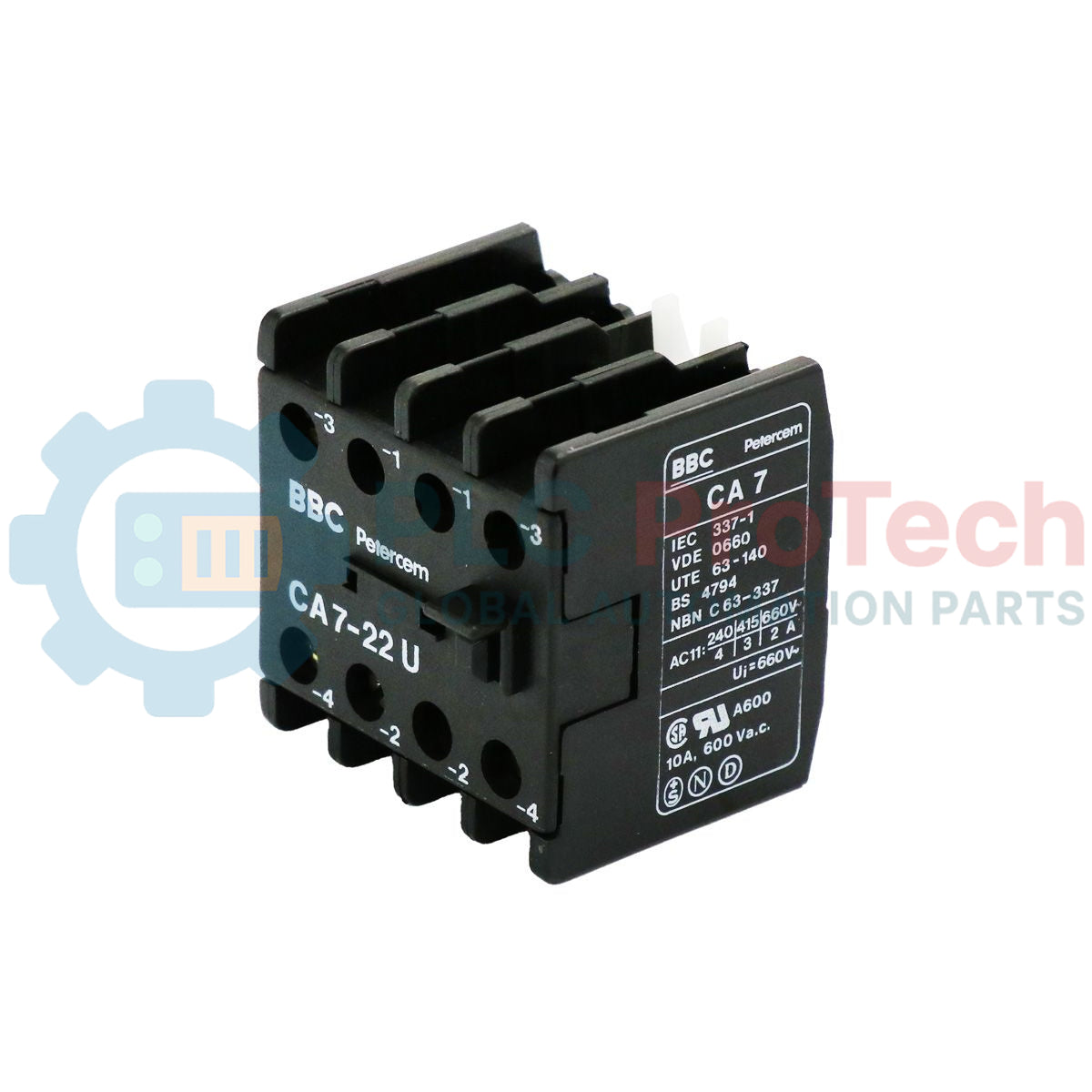
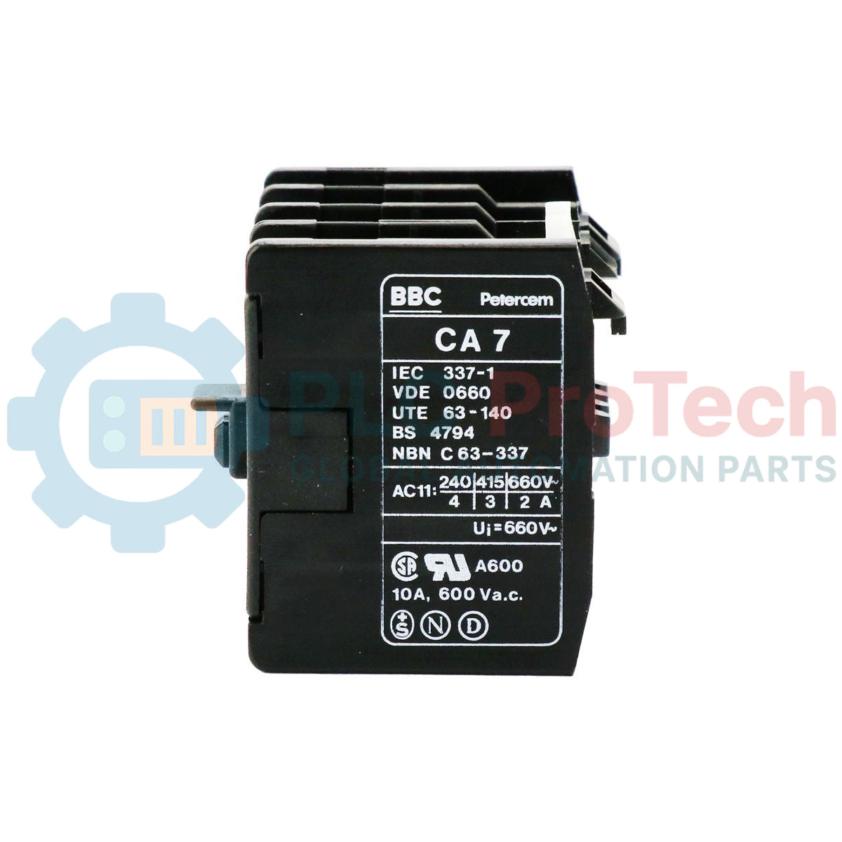
Engineered for seamless integration into industrial control architectures, the ABB CA7-22U provides reliable auxiliary contact feedback to monitor contactor state transitions. This front-mounted contact block features a highly dependable mechanical linkage that synchronizes precisely with the parent contactor's main poles. Constructed with robust industrial-grade housing, it is optimized to provide precise feedback signals to PLC inputs, safety interlock systems, and control circuit indicators under demanding operational conditions.
Key Features
-
Balanced Contact Configuration: Equipped with 2 Normally Open (NO) and 2 Normally Closed (NC) auxiliary contacts for flexible circuit design.
-
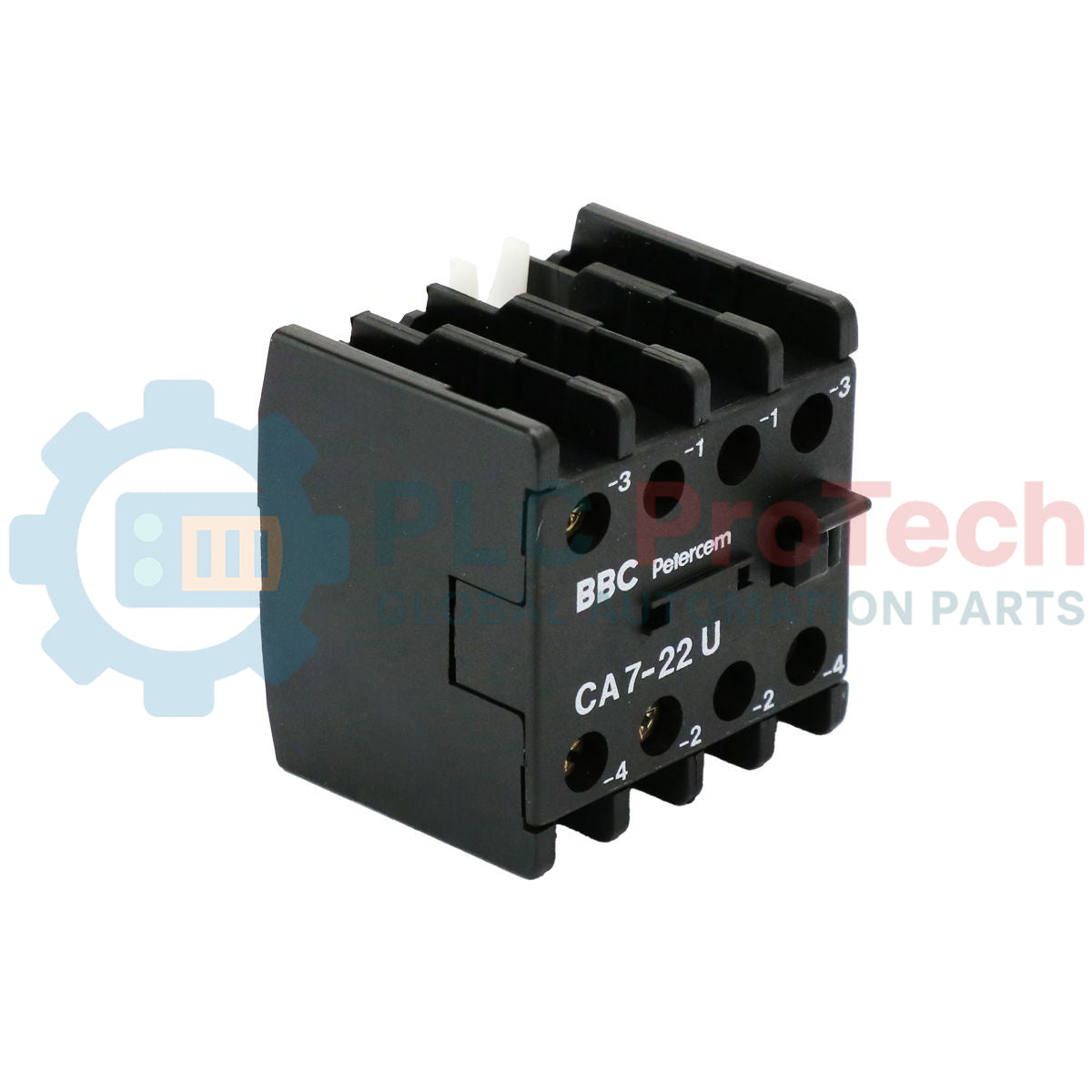
Snap-On Front Mounting: Easily installs directly onto the front of compatible contactors without requiring specialized tools or mounting hardware.
-
High-Integrity Control Feedback: Designed to offer low contact resistance and highly repeatable switching for safety interlocks and status signaling.
-
Compact Footprint: Standardized form factor minimizes panel depth utilization, allowing clean wire routing in crowded control enclosures.
Applications
- Motor control center (MCC) starter assemblies and control panels.
- Electrical interlocking systems for reversing contactors and star-delta starters.
- State feedback signaling to PLC input modules and distributed control systems (DCS).
- Auxiliary alarm and fault circuit activation in power distribution panels.
Technical Specifications
| Parameter |
Specification |
| Manufacturer |
ABB |
| Model Number |
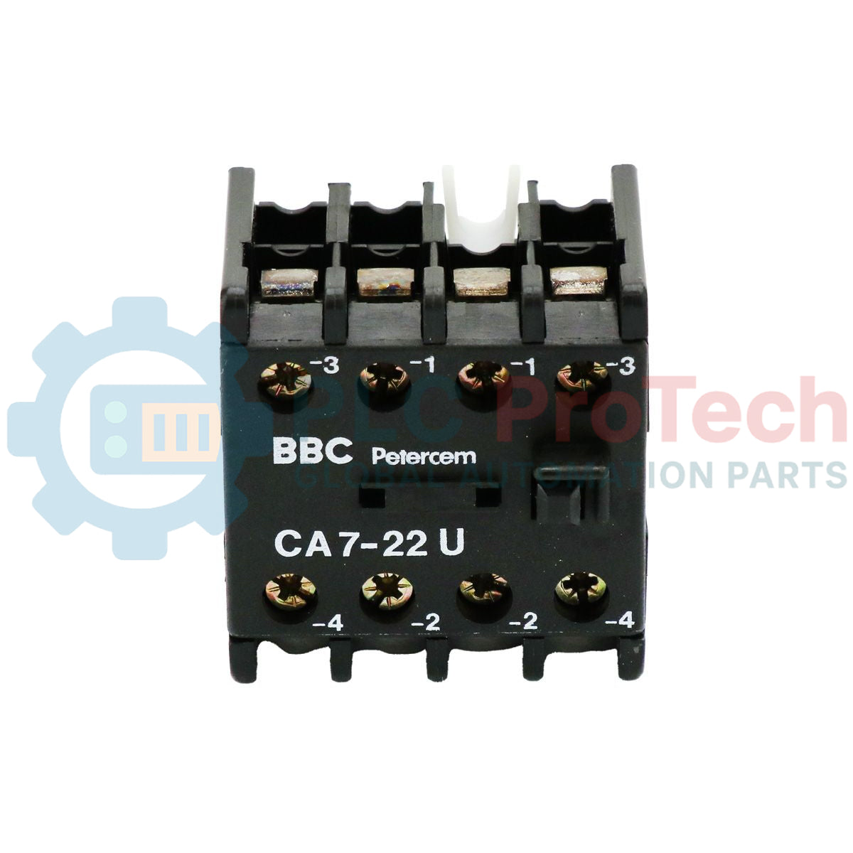
CA7-22U |
| Product Type |
Auxiliary Contact Block |
| Contact Arrangement |
2 NO (Normally Open) + 2 NC (Normally Closed) |
| Mounting Method |
Front Snap-On |
| Commodity Code |
85371091 |
| Shipping Weight (Calculated) |
0.50 kg |
| Package Dimensions (Calculated) |
80 mm x 50 mm x 60 mm |
Empirical Engineering Insights
Alternative Models & Compatibility
Verify the physical mating interface of your main contactor frame before procurement. Ensure that the actuator mechanism aligns cleanly with the front-mounting guide rail of the contactor to prevent uneven mechanical wear on the auxiliary contact sliders.
Application Pitfalls & Engineering Notes
When routing these contacts to low-voltage PLC digital input modules (such as 24 VDC systems), be mindful of minimum switching current requirements. Standard power auxiliary contacts can develop microscopic surface oxidation in high-humidity or corrosive atmospheres, which may lead to intermittent signal loss if circuit currents are below 10 mA.
Commissioning & Wiring Tips
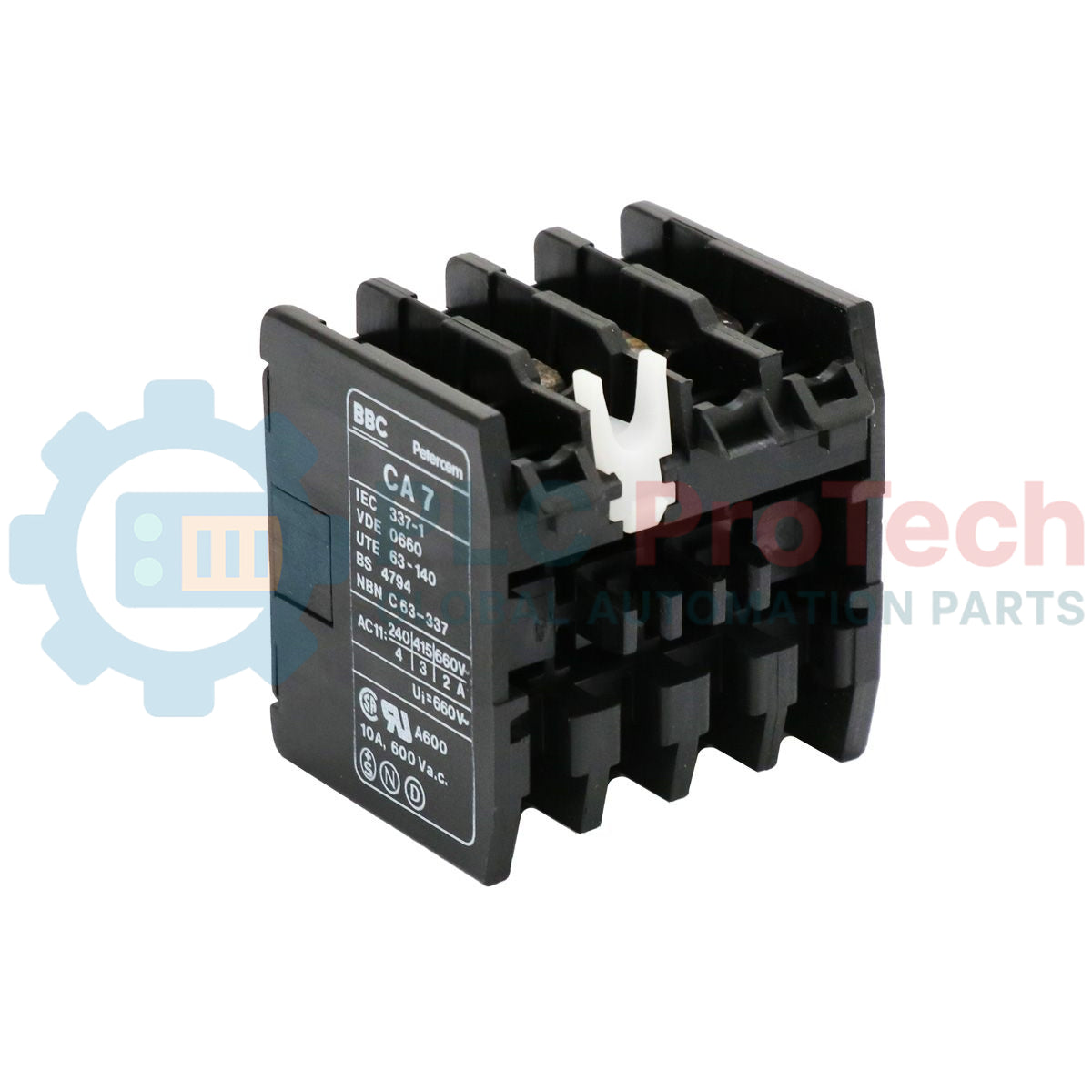
Always perform a manual mechanical actuation test post-installation to confirm that the auxiliary contact block moves in complete synchronization with the contactor's solenoid assembly. Ensure wiring harness tension does not pull the auxiliary block away from its snapped seating position, as this can lead to incomplete contact closure.
Installation Guidelines
CRITICAL WARNING:
De-energize the entire control panel and isolate all main and control power circuits prior to installing or removing the auxiliary contact block. Confirm the absence of hazardous control voltages using a calibrated voltmeter. Failure to isolate power can result in severe electrical shock or unexpected machinery startup.
1
Isolate the control circuit supply and verify that the contactor is physically in the de-energized (open) position.
2
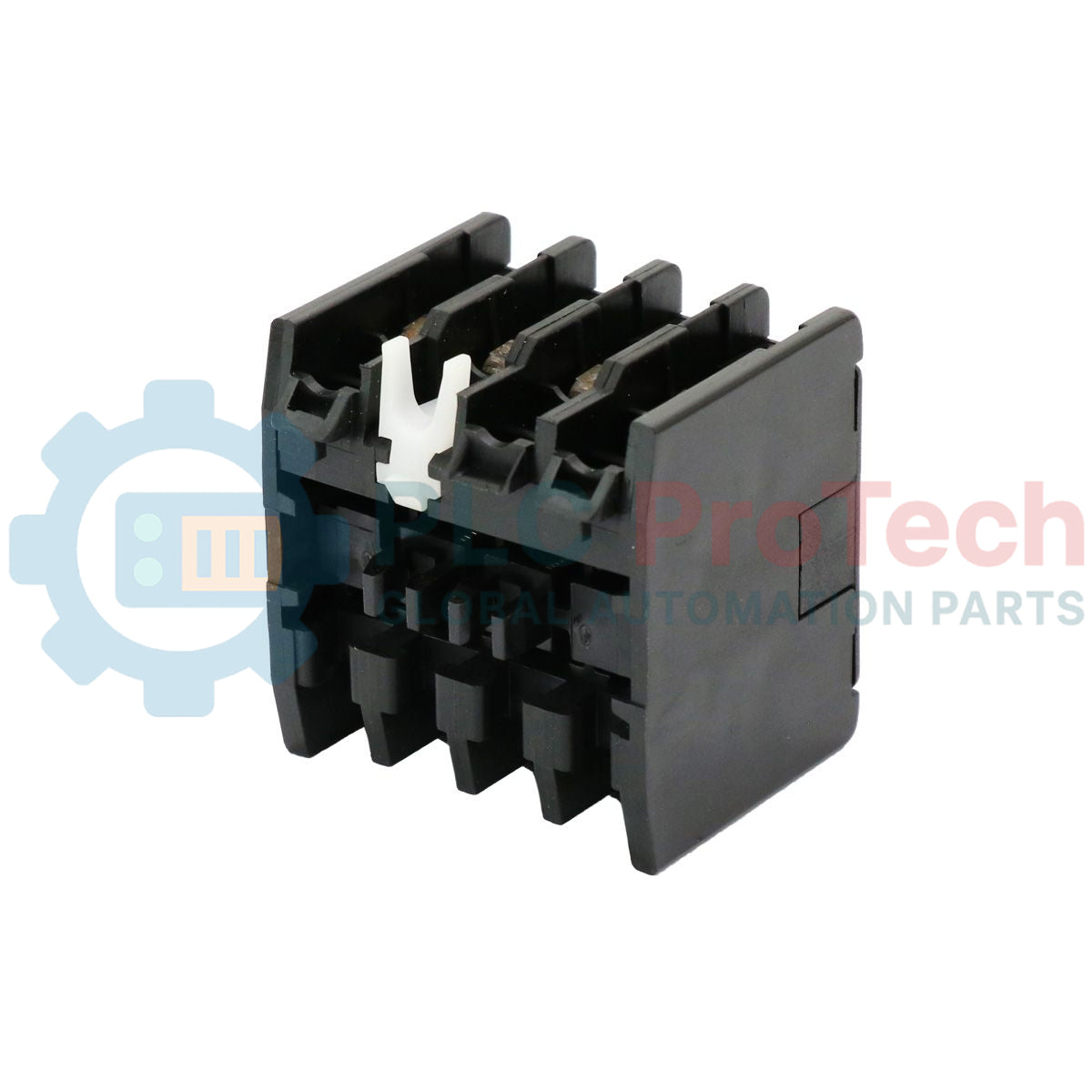
Align the guide pins on the rear of the CA7-22U block with the corresponding front slot interface of the parent contactor.
3
Apply firm, even pressure straight down until the locking tab snaps and securely clicks into position.
4
Terminate control wiring to the screw terminals, ensuring wires are stripped to the proper length and torqued to specifications without over-tightening.