Description
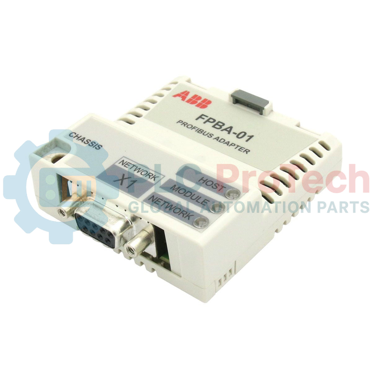
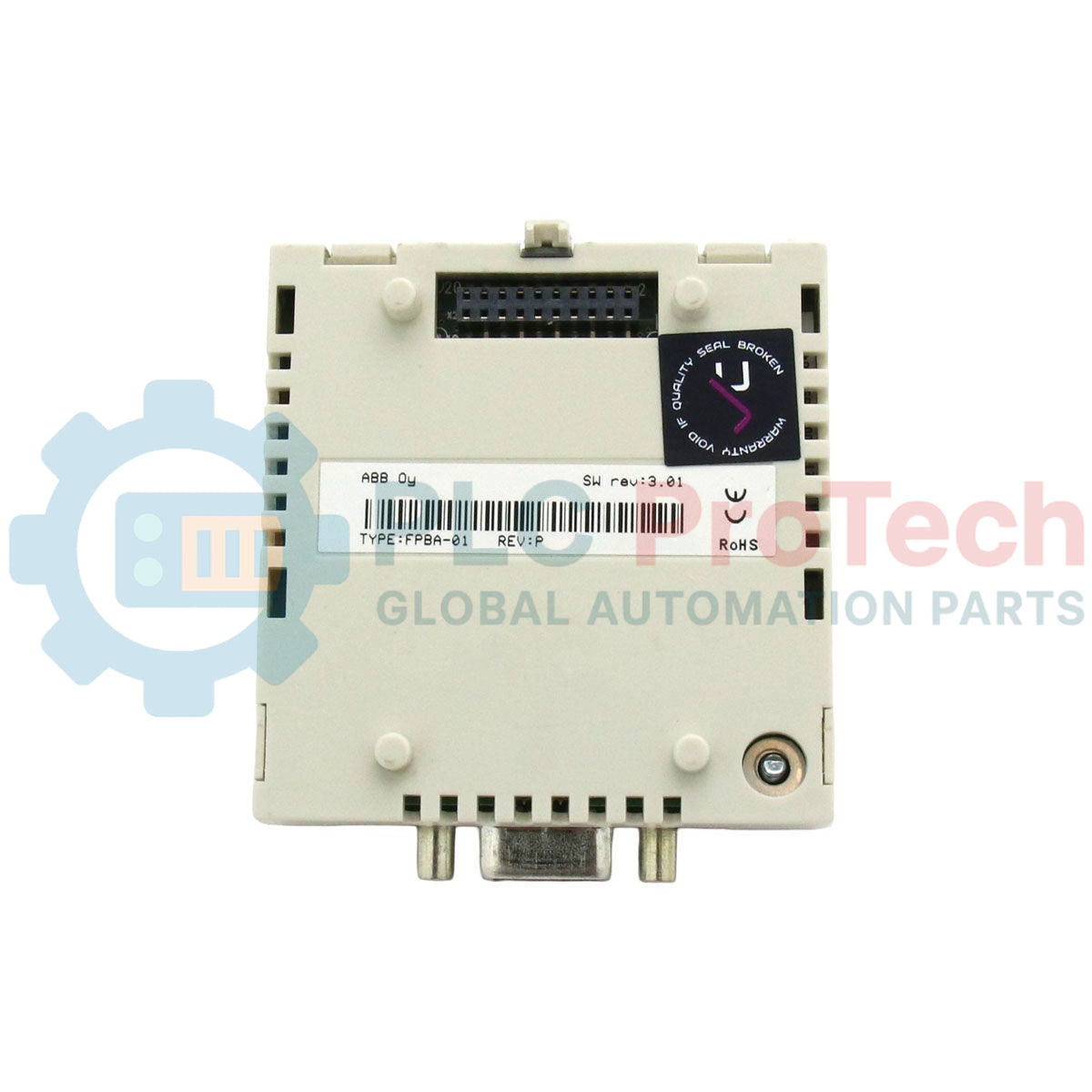
Establishing high-performance cyclic and acyclic data exchange between industrial control networks and variable speed drives, the ABB FPBA-01 PROFIBUS DP communication adapter module provides seamless integration into distributed control architectures. This interface module slides directly into the drive slot, enabling standard PROFIdrive or ABB Drives communication profiles to command, monitor, and configure parameters on compatible frequency converters. Operating with 16-bit word lengths, it ensures reliable signal transmission under demanding electromagnetic conditions typical of industrial plant floors.
Key Technical Features
-
Multi-Protocol Support: Full compliance with both PROFIBUS DP-V0 and DP-V1 standards, allowing cyclic process data exchange and acyclic parameter configuration.
-
Adaptive Baud Rate Detection: Automatically locks onto network speeds ranging from 9.6 kbit/s up to 12 Mbit/s, eliminating manual transmission rate configurations.
-
Versatile Control Profiles: Native support for the standard PROFIdrive profile as well as the proprietary ABB Drives profile for system flexibility.
-
Direct Slot Integration: Compact physical form factor designed to mount inside the drive housing, receiving internal control power directly from the host drive.
Industrial Applications
-
Continuous Process Environments: Connecting variable speed pump and fan drives in water/wastewater facilities to centralized PLCs.
-
Automated Material Handling: Synchronization of conveyor speed controllers in packaging and logistics distribution lines.
-
Machinery Manufacturing: High-density multi-axis machinery configurations using ACS355 drive blocks controlled via a centralized Siemens master controller.
Technical Specifications Table
| Parameter Specification |
Value / Limit |
| Manufacturer |
ABB |
| Model Identifier |
FPBA-01 |
| Internal Part Code |
68469325 |
| Host Drive Compatibility |
ACS355, ACS350, ACS850, ACQ810, ACS880, ACS580 Series |
| Communication Protocol |
PROFIBUS DP-V0 and DP-V1 |
| Baud Rate Range |
9.6 kbit/s to 12 Mbit/s (Auto-detecting) |
| Connection Interface |
9-pin D-sub (female) connector |
| Current Consumption |
Max 80 mA at 24 VDC (supplied from host drive) |
| Commodity Code |
85044095 |
| Dimensions |
7.60 cm x 7.60 cm x 2.50 cm |
| Net Weight |
0.10 kg |
Connections and Pin Assignments
The fieldbus physical layer utilizes a 9-pin Sub-D female block configured as follows:
| Pin Number |
Signal Name |
Description |
| 1 |
SHLD |
Chassis and Cable Shield Connection |
| 3 |
RxD/TxD-P (B-Line) |
Positive Data Transmission (Red Wire) |
| 5 |
DGND |
Data Ground (Reference potential) |
| 6 |
VP |
+5 VDC Power supply for termination resistors |
| 8 |
RxD/TxD-N (A-Line) |
Negative Data Transmission (Green Wire) |
Empirical Engineering Insights
Alternative Models & Compatibility
The FPBA-01 acts as a universal communication adapter for multiple series of ABB drives. However, some legacy ACS350 drives require a dedicated firmware revision level to map DP-V1 acyclic blocks correctly. Check parameter group 51 (Fieldbus Parameter Group) after hardware discovery to confirm that the driver version is recognized by the VFD main board.
Application Pitfalls & Engineering Notes
A common cause of bus faults during system startups is the lack of proper network termination on physical line ends. If the FPBA-01 sits at the physical end of the PROFIBUS segment, a SUB-D connector containing integrated termination switches must be used, and the switch must be toggled to 'ON'. Ensure that this termination connector receives power from Pin 6 (+5V) and Pin 5 (DGND) on the FPBA-01 module.
Commissioning & Wiring Tips
When compiling the master PLC database, ensure the correct GSD configuration file is loaded (typically ABB_090F.GSD). After altering parameter values in Group 51, a parameter refresh is mandatory. Trigger Parameter 51.27 (FBA PAR REFRESH) or perform a complete drive power cycle to commit the node address changes to active memory.
Installation Guidelines
CRITICAL SAFETY WARNING
Ensure the host drive is fully de-energized. Wait a minimum of 5 minutes after switching off the main incoming power supply to allow the DC bus capacitors to discharge completely. Use a calibrated multimeter to confirm zero voltage at the drive terminals before inserting or removing the communication card.
1
Align the male multi-pin header on the rear of the FPBA-01 adapter with the corresponding interface option slot on the host drive control panel area.
2
Carefully press the module in place until the retaining plastic tabs engage with the drive frame to secure physical placement.
3
Tighten the integrated mounting/grounding screw to establish reliable chassis grounding and prevent vibration-induced disconnections.
4
Insert the standard 9-pin Sub-D PROFIBUS connector and secure it using the thumb screws. Route the fieldbus cable far from high-power phase wiring.