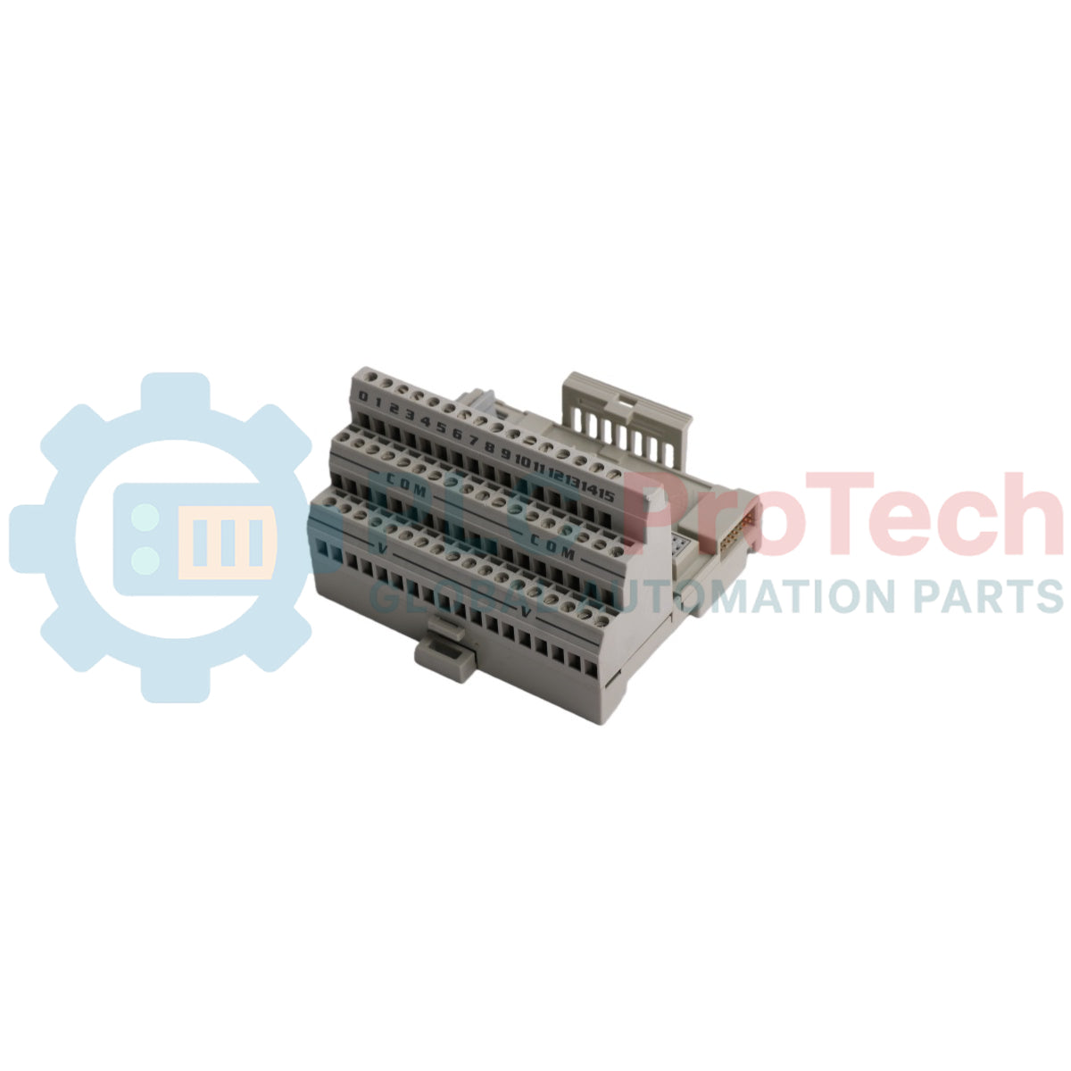
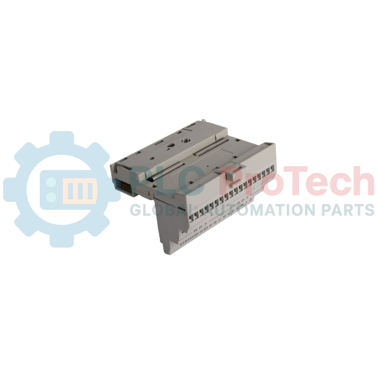
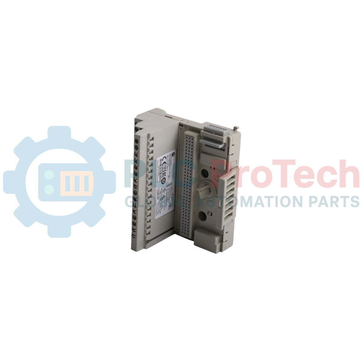
1794-TB3K یک قطعه نصب و سیمکشی تخصصی و مقاوم است که برای پلتفرم مدولار توزیعشده FLEX I/O طراحی شده است. این قطعه سختافزاری صنعتی، پیکربندی پایه ضروری برای مجموعههای ترمینال ورودی/خروجی از راه دور را تشکیل میدهد و نقاط سیمکشی حسگر/عملگر در سمت میدانی را با ماتریس باس بکپلن یکپارچه ترکیب میکند. این نسخه خاص دارای پوشش محافظ کارخانهای است که مدارهای داخلی را در برابر عوامل خورنده جوی، رطوبت و آلودگیهای هوایی که معمولاً در محیطهای عملیاتی سخت وجود دارند، محافظت میکند.
واحد مجهز به پیکربندی بلوک ترمینال سهلایه است که سی و شش پیچ ترمینیشن جداگانه برای مدیریت سیگنالهای گسسته یا آنالوگ، مسیرهای توزیع برق و خطوط زمین مشترک به صورت جداگانه فراهم میکند. 1794-TB3K از طریق کانکتور یکپارچه نر/ماده FlexBus در کنار هم، پیوندهای ساختاری بکپلن را برقرار میکند و انتقال مداوم داده و برق را در کل خوشه مدولار محلی امکانپذیر میسازد. این محصول در صنایع پردازش سنگین مانند تصفیه فاضلاب، سکوهای حفاری دریایی، کارخانههای فرآوری خمیر و کاغذ و تأسیسات سنتز شیمیایی که نیازمند مقاومت در برابر تخریب محیطی هستند، استاندارد است.
ویژگیها
پوشش محافظ کارخانهای که مقاومت در برابر خوردگی و رطوبت را برای اطمینان از عملکرد در محیطهای سخت افزایش میدهد.
طراحی سهلایه ترمینیشن که خطوط سیگنال فعال، مسیرهای تغذیه و اتصالات بازگشت زمین را جدا میکند.
کانکتورهای یکپارچه کشویی و قفلشونده FlexBus که مقیاسپذیری بکپلن مدولار را روی یک ریل امکانپذیر میسازد.
طراحی عملیاتی مستقل که امکان تعویض داغ ماژولهای پردازشی بدون جدا کردن سیمکشی میدانی را فراهم میکند.
کلیدهای مکانیکی داخلی برای تراز دقیق ماژولها و نصب فیزیکی ایمن.
کاربردها
پنلهای کنترل فرآوری تصفیه فاضلاب و پساب.
کارخانههای تصفیه شیمیایی و دستهبندی مواد شیمیایی خورنده.
سکویهای فرآوری دریایی و نصبهای اتوماسیون ساحلی.
ماشینآلات فرآوری خمیر کاغذ، کاغذ و آسیاب مواد معدنی سنگین.
مشخصات فنی
پارامتر
مشخصات
تولیدکننده
Rockwell Automation / Allen-Bradley
برند
FLEX I/O
شماره قطعه
۱۷۹۴-TB3K
نوع قطعه
واحد پایه ترمینال با پوشش محافظ
نوع ترمینیشن
ترمینالهای گیره پیچ سه طبقه
تعداد نقاط ترمینال
36
ظرفیت اندازه سیم
سیم مسی جامد یا رشتهای با سایز ۰.۳۴ تا ۲.۵ میلیمتر مربع (۲۲ تا ۱۲ AWG)
گشتاور پیچ ترمینال
گشتاور پیچ ترمینال ۰.۵۶ تا ۰.۷۹ نیوتنمتر (۵.۰ تا ۷.۰ پوند-اینچ)
رتبه ولتاژ
حداکثر ۳۱.۲ ولت DC / ۱۳۲ ولت AC
ظرفیت جریان
حداکثر ۱۰ آمپر برای هر باس تغذیه، حداکثر ۲ آمپر برای هر ترمینال سیگنال
نوع حفاظت
زیرلایه برد مدار با پوشش محافظ
دمای کاری
۰ تا ۵۵ درجه سانتیگراد
دمای نگهداری
-۴۰ تا ۸۵ درجه سانتیگراد
رطوبت نسبی
۵٪ تا ۹۵٪ بدون تراکم
کشور سازنده
ایالات متحده آمریکا
وزن
۰.۱۴ کیلوگرم
ابعاد
۹۴ میلیمتر × ۹۴ میلیمتر × ۶۹ میلیمتر
اتصالات/رابطها
نامگذاری ردیف ترمینالها
تخصیص عملکرد / ترمینیشن
ردیف A (طبقه بالا)
گرههای اتصال سیم سیگنال ورودی/خروجی ۰ تا ۱۵
ردیف B (طبقه میانی)
ترمینالهای توزیع ولتاژ منبع تغذیه (+V)
ردیف C (طبقه پایین)
لینکهای مشترک مرجع سیگنال و اتصال زمین شاسی (COM/GND)
راهنمای نصب
نصب روی ریل DIN
چنگکهای نصب بالایی پشت بلوک مونتاژ را روی لبه بالایی ریل DIN استاندارد ۳۵ میلیمتری گالوانیزه قرار دهید. لبه پایینی محفظه را محکم به سمت پایین و داخل فشار دهید تا گیره فلزی فنردار روی ریل پایین قفل شود.
اتصال بکپلن
پینهای نری جانبی FlexBus واحد جدید را با سوکت مادگی متناظر ماژول موجود یا آداپتور شبکه روی ریل تراز کنید. پایه را به صورت جانبی حرکت دهید تا دو محفظه کاملاً به هم متصل شده و گیرههای قفلکننده درگیر شوند.
اتصال سیمکشی میدان
عایق سیمهای ورودی میدان را به طول تقریبی ۷ میلیمتر جدا کنید. سیم مسی لخت را کاملاً در محل گیره پیچ مشخص شده وارد کرده و پیچ ترمینال را با گشتاور بین ۰.۵۶ تا ۰.۷۹ نیوتنمتر محکم کنید.
حفظ حفاظت در برابر خوردگی
در صورت خالی ماندن اسلاتهای مجاور روی ریل DIN، صفحات محافظ روی اتصالات رابط FlexBus را نگه دارید. هنگام تمیز کردن یا تعویض ماژول، از خراشیدن برد پایه داخلی خودداری کنید تا از آسیب دیدن لایه فیلم پوشش محافظ کارخانه جلوگیری شود.
سؤالات متداول
چه چیزی این واحد پایه را از مدل استاندارد 1794-TB3 متمایز میکند؟
این واحد دارای لایه پوشش محافظ کارخانهای روی اجزای برد مدار داخلی است تا محافظت اضافی در برابر آلودگیهای محیطی شدید فراهم کند.
آیا میتوان این واحد را با ماژولهای بدون پوشش محافظ روی همان ریل ترکیب کرد؟
بله، از نظر فیزیکی و الکتریکی با ماژولهای استاندارد سازگار است، اگرچه کل سیستم باید پوشش داده شود تا مقاومت کامل محیطی حاصل شود.
بلوکهای ترمینال سیمهای مسی جامد یا رشتهای با اندازه ۲۲ AWG تا ۱۲ AWG را میپذیرند.
آیا این قطعه از تعویض داغ ماژولهای ورودی/خروجی عملیاتی پشتیبانی میکند؟
بله، این امکان را میدهد که ماژولهای کاربردی الکترونیکی بدون نیاز به قطع سیمهای میدان یا خاموش کردن آداپتور باس، در حین برقدار بودن جدا و نصب شوند.
آیا منبع تغذیه خارجی مستقیماً به این بلوک ترمینال متصل میشود؟
بله، ولتاژ تغذیه حسگر و عملگر سمت میدان باید به ترمینالهای ردیف B متصل شود تا برق در نقاط ماژول توزیع شود.
حداکثر جریان مجاز برای هر ترمینال سیگنال چقدر است؟
هر پیچ ترمینال سیگنال مستقل قادر است جریان پیوسته تا ۲ آمپر را تحمل کند.
واحد چگونه به کنترلکننده منطقی برنامهپذیر اصلی سیستم متصل میشود؟
این واحد از طریق ماژول آداپتور ارتباطی که در سمت چپترین موقعیت مسیر ریل DIN محلی قرار دارد، به کنترلکننده اصلی متصل میشود.
آیا این واحد میتواند حلقههای ابزار دقیق جریان متناوب را پشتیبانی کند؟
بله، طراحی عایق الکتریکی اجازه میدهد سیگنالها تا حداکثر ۱۳۲ ولت AC سوئیچ شوند.
برای نصب پایه روی ریل DIN چه ابزارهایی لازم است؟
برای نصب نیازی به ابزار نیست، زیرا واحد مستقیماً روی ریل نصب میشود، اما میتوان از پیچگوشتی سر تخت برای باز کردن قفل پایین هنگام جدا کردن استفاده کرد.
حداکثر توصیه گشتاور برای پیچهای گیره ترمینال چقدر است؟
پیچها باید تا مقداری در بازه ۰.۵۶ تا ۰.۷۹ N-m سفت شوند تا از آسیب دیدن جلوگیری شود و در عین حال مقاومت تماس پایین حفظ شود.
راهنمای عملی برای جایگزینی ایستگاههای اپراتور بیلی سیمفونی قدیمی که بر روی OpenVMS Alpha اجرا میشوند. این راهنما مقایسهای بین شبیهسازی Alpha، مهاجرت OpenVMS به x86، بازپلتفرمسازی OPC و نوسازی...
دادههای نگهداری و تعمیرات، سفارشهای کاری، سیگنالهای حسگر، تاریخچه داراییها، هزینهها و دانش تکنسین را به هم متصل میکند. استفاده صحیح از آن، برنامهریزی، قابلیت اطمینان، نگهداری پیشبینیشده،...
این مقاله توضیح میدهد که چگونه عملگرهای الکتریکی یکپارچه، مانند سری e-Actuator شرکت SMC، با جایگزینی سیستمهای پنوماتیک و هیدرولیک سنتی، کنترل حرکت صنعتی را متحول میکنند. این مقاله به بهبود دقت...
این مقاله توضیح میدهد که چگونه سیستمهای PLC عملیات ریاضی اصلی مانند جمع، تفریق، ضرب، تقسیم، مدولو و توان را در اتوماسیون صنعتی انجام میدهند. نشان میدهد که چگونه این بلوکهای عملکردی سیگنالهای...
این مقاله چندین تابع پیشرفته منطق بولی را که در برنامهنویسی PLC فراتر از عملیات پایه AND، OR و NOT استفاده میشوند، توضیح میدهد. همچنین نحوه استفاده از ابزارهایی مانند جداول صحت، مالتیپلکسرها،...
منطق بولی پایه و اساس هر برنامه PLC است. از کنترلهای ساده ماشین تا سیستمهای پیچیده اتوماسیون صنعتی، دروازههای منطقی تعیین میکنند که کنترلکنندهها چگونه به ورودیها و شرایط عملیاتی متغیر پاسخ...
انتخاب یک گزینه باعث بارگذاری مجدد کامل صفحه میشود.