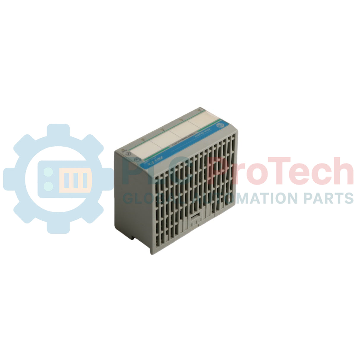
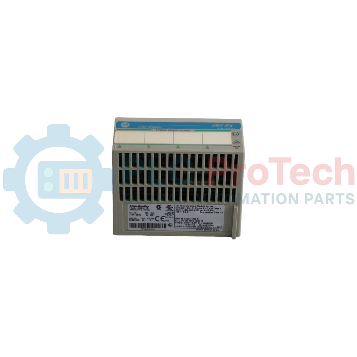
آلن-برادلی 1797-OB4D یک ماژول خروجی دیجیتال ایمن ذاتی با عملکرد بالا است که برای محیطهای صنعتی مناطق خطرناک طراحی شده است. این ماژول بخشی از خانواده محصولات FLEX Ex I/O است و ۴ خروجی غیر ایزوله منبع تغذیه را ارائه میدهد که به طور خاص برای راهاندازی دستگاههای دیجیتال میدانی مانند شیرها، آلارمهای صوتی و سلونوئیدها مهندسی شده است.
این ماژول دارای رابط ارتباطی یکپارچه FlexBus است که بهطور بینقص از طریق آداپتورهای سازگار مانند آداپتور ControlNet Ex (1797-ACNR15) ارتباط برقرار میکند تا مکانیزم دو سطحی خطا را در سراسر بکپلین ایجاد کند. این محصول به صورت تجهیزات باز عرضه میشود و باید روی واحد پایه ترمینال ایمن ذاتی 1797-TB3 یا 1797-TB3S در داخل یک محفظه مناسب نصب شود تا حداکثر ایمنی سیستم و جداسازی محیطی تضمین شود.
معماری الکتریکی شامل نشانگرهای تشخیصی و پروفایلهای پیکربندی نرمافزاری پیشرفته قابل دسترسی از طریق RSLogix 5000 است. هر کانال منبع به صورت الکتریکی به یکدیگر متصل است و حفاظت الکترونیکی پیشرفته به همراه فیلتر آلارم قابل انتخاب را شامل میشود، که این ماژول را برای صنایع پتروشیمی، شیمیایی، گاز و فرآیندهای خودکار در طبقهبندیهای منطقه ۱، منطقه ۲ یا منطقه ۲۲ ایدهآل میسازد.
ویژگیها
ساخته شده با ۴ خروجی دیجیتال ایمن ذاتی غیر ایزوله و منبع تغذیه.
طراحی شده برای تعویض داغ، امکان جداسازی و نصب ایمن در شرایط برقدار در محیطهای غیرخطرناک.
قابلیتهای تشخیص جامع برای هر کانال شامل تشخیص قطع سیم و اضافه بار.
فیلتر ۱۰۰ هرتز (۱۰ میلیثانیه) قابل تنظیم نرمافزاری و زمانهای ثابت فیلتر آلارم قابل تنظیم (۰.۲۵ میلیثانیه تا ۳۲ میلیثانیه).
رفتارهای خطای خروجی قابل انتخاب که اجازه میدهد کانالها یا به صفر بازنشانی شوند یا آخرین حالت معتبر را حفظ کنند.
تشخیص فیزیکی واضح با ۴ نشانگر وضعیت زرد، ۴ نشانگر خطای قرمز و ۱ نشانگر قدرت ماژول سبز.
حفاظت الکترونیکی داخلی شامل قطع سیم، شرایط اضافه بار و اتصال کوتاه.
طراحی حالت جامد با استفاده از اتصال استاندارد FlexBus و القای داخلی ناچیز.
کاربردها
کنترل خودکار شیرهای کنترل پنوماتیک و هیدرولیک ایمن ذاتی.
کنترل و راهاندازی آلارمهای صوتی و نشانگرهای بصری نصب شده در محلهای انفجاری.
فعالسازی سلونوئیدها و سیمپیچهای رله با توان پایین در جوهای گازی یا گرد و غبار خطرناک.
استقرار اتوماسیون فرآیند در کارخانههای فرآوری شیمیایی، پالایشگاههای نفت و تأسیسات بالادستی گاز.
پردازش سیگنال ایمن در محیطهای حمل غلات یا فرآوری پودر مطابق با معیارهای منطقه ۲۲ گرد و غبار.
مشخصات فنی
ویژگی
مقدار
تولیدکننده
آلن-برادلی / راکول اتوماسیون
مدل
1797-0B4D
سری محصول
FLEX Ex I/O
تعداد خروجیها
4 خروجی غیر ایزوله، منبع تغذیه
نوع خروجی IS
Ex ia IIB/IIC T4، AEx ia IIC T4، کلاس I، II، III تقسیم 1 گروههای A، B، C، D، E، F، G T4
نوع ماژول IS
Ex ib IIB/IIC T4، AEx ib IIC T4، کلاس I تقسیم 1 گروههای A...D T4
محدوده بار
30...5000 اهم
تشخیص خطا
بیتهای خطا در جدول داده و چشمک زدن LED قرمز (برای هر کانال) با فرکانس 1 هرتز
Ui < 5.8V DC، Ii < 400 mA، Li = ناچیز، Ci < 1.35 میکروفاراد
نوع منبع تغذیه
+V، -V ایمن ذاتی
پارامترهای منبع تغذیه
Ui < 9.5V DC، Ii < 1 A، Li = ناچیز، Ci = ناچیز
مصرف توان سمت میدان ماژول
7.5 W
تبعیض توان
5 W
تبعیض حرارتی
17.07 BTU/hr
محل ماژول
واحد پایه ترمینال 1797-TB3 یا 1797-TB3S
حداکثر اندازه سیم هادی
سیمهای رشتهای 4 میلیمتر مربع (سایز 12) با عایق 1.2 میلیمتر (3/64 اینچ)
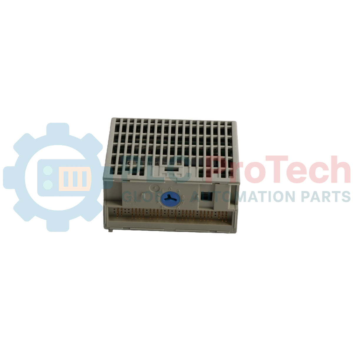
موقعیت کلید سوئیچ
موقعیت 7
دمای عملکرد
-20...+70 درجه سانتیگراد (-4...+158 درجه فارنهایت)
دمای ذخیرهسازی
-40...+85 درجه سانتیگراد (-40...+185 درجه فارنهایت)
رطوبت نسبی
رطوبت نسبی 5...95% بدون تراکم
ضربه در حالت عملکرد / غیرعملکردی
تست شده با شتاب اوج 15 g، عرض پالس 11(+1) میلیثانیه
لرزش
تست شده با 2 g در فرکانس 10...500 هرتز طبق IEC68-2-6
ابعاد (ارتفاع × عرض × عمق)
46 × 94 × 75 میلیمتر (1.8 × 3.7 × 2.95 اینچ)
وزن
تقریباً 200 گرم (7.05 اونس)
اتصالات/رابطها
پین ترمینال
عملکرد
ردیف A - ترمینال 0
اتصال خروجی کانال 0 (+)
ردیف A - ترمینال 1
اتصال خروجی کانال 0 (-)
ردیف A - ترمینال 4
اتصال خروجی کانال 1 (+)
ردیف A - ترمینال 5
اتصال خروجی کانال 1 (-)
ردیف A - ترمینال 8
اتصال خروجی کانال 2 (+)
ردیف A - ترمینال 9
اتصال خروجی کانال 2 (-)
ردیف A - ترمینال 12
اتصال خروجی کانال 3 (+)
ردیف A - ترمینال 13
اتصال خروجی کانال 3 (-)
ردیف C - ترمینال 34
+V ورودی تغذیه ایمن ذاتی DC
ردیف C - ترمینال 35
-V ورودی تغذیه ایمن ذاتی مشترک DC
ردیف C - ترمینال 50
+V ترمینال توسعه زنجیره دنبالهای تغذیه DC
ردیف C - ترمینال 51
-V ترمینال توسعه زنجیره دنبالهای تغذیه DC مشترک
توجه: ترمینالهای 2، 3، 6، 7، 10، 11، 14، 15، 17 تا 32، 36، 37، 38، 39، 46، 47، 48 و 49 استفاده نمیشوند و اتصال به آنها مجاز نیست. از استفاده از ترمینالهای بلااستفاده به عنوان ترمینالهای پشتیبان خودداری کنید تا از آسیب به سیستم جلوگیری شود.
راهنمای نصب
مشخصات محفظه: ماژول باید هنگام استفاده در منطقه 1 در یک محفظه فلزی با درجهبندی مناسب نصب شود تا از آن در برابر شرایط محیطی محافظت شود، زیرا خود ماژول دارای درجه حفاظتی IP20 است.
انتخاب کابینت منطقه 22: برای نصب در محیطهای دارای گرد و غبار منطقه 22، باید از مدلهای کابینت دارای گواهی خاص استفاده شود: IVK-ISRPI-V16LC، IVK-ISRPI-V8HYW، یا IVK-ISRPI-V8LC.
تراز کلید سوئیچ: قبل از نصب ماژول، کلید سوئیچ روی واحد پایه ترمینال را به سمت ساعتگرد تا موقعیت 7 بچرخانید. پس از اتمام پیکربندی سیمکشی، این تنظیم کلید سوئیچ را تغییر ندهید.
تنظیم FlexBus: اطمینان حاصل کنید که کانکتور FlexBus کاملاً به سمت چپ و به سمت واحد پایه یا آداپتور مجاور فشار داده شده است قبل از تلاش برای وارد کردن ماژول؛ اجرا مسدود میشود مگر اینکه کاملاً کشیده شده باشد.
تراز و نشستن پینها: اطمینان حاصل کنید که تمام پینهای اتصال پایین صاف هستند، نوار تراز ماژول را با شیار تراز روی پایه همراستا کنید و با فشار محکم پایین بیاورید تا مکانیزم قفل به طور ایمن قفل شود.
جداسازی ایمنی ذاتی: فقط پایههای ترمینال ایمنی ذاتی را به سایر ماژولها/آداپتورهای سیستم ایمنی ذاتی متصل کنید تا یکپارچگی بکپلین حفظ شود.
سایهبان و زمین: تمام سیمکشیهای ورودی/خروجی باید از سیمهای با کیفیت بالا و دارای شیلد استفاده کنند. تمام شیلدهای سیم باید به طور دقیق خارج از ماژول با استفاده از نوارهای باس اختصاصی یا نقاط عبور شیلد خاتمه یابند.
جلوگیری از الکتریسیته ساکن: کل سیستم باید در برابر بارهای الکتریسیته ساکن محافظت شود. یک علامت هشدار بسیار قابل مشاهده در نزدیکی نصب کنید که نوشته باشد: «هشدار: از بار الکتریسیته ساکن خودداری کنید».
محدودیتهای برق: سیستم باید فقط توسط منبع تغذیه ایمنی ذاتی تغذیه شود. هرگز اجازه ندهید سیگنالهای غیر ایمنی ذاتی به ماژول اعمال شود، زیرا این کار وضعیت ایمنی ذاتی آن را به طور دائمی باطل میکند.
قوانین نصب زنده: اگرچه ماژول از حذف و نصب در حالت روشن پشتیبانی میکند، قوس الکتریکی ممکن است در صورت جدا شدن یا سیمکشی پایه ترمینال زیرین در حالی که برق میدان فعال است، رخ دهد که خطر انفجار در مناطق خطرناک ایجاد میکند. اطمینان حاصل کنید که برق کاملاً قطع شده یا محیط به عنوان غیرخطرناک تأیید شده باشد قبل از دست زدن به آن.
انطباق و گواهیها
CENELEC: II (1) 2G Ex ib[ia] IIC T4، II (1) D [Ex iaD]
UL, C-UL: تأیید شده برای کلاس I، گروههای A، B، C، D؛ کلاس II، گروههای E، F، G؛ مکانهای خطرناک کلاس III؛ کلاس I، منطقه 1، AEx ib[ia] IIC T4
FM: ایمنی ذاتی کلاس I، بخش 1، گروههای A، B، C، D، T4؛ تجهیزات مرتبط با اتصالات ایمنی ذاتی کلاس I، II، III، بخش 1، گروههای A-G؛ کلاس I، منطقه 1، AEx ib[ia] IIC T4
ATEX: شماره گواهی مرجع DMT 02 ATEX E 040 X مطابق با استانداردهای EN 60079-0، EN 60079-11 و سری EN 61241
دستورالعملهای علامت CE: تأیید شده برای نصب در مناطق اتحادیه اروپا و منطقه اقتصادی اروپا طبق دستورالعمل EMC 2014/30/EU با اعمال استانداردهای EN 61000-6-4:2007، EN 61000-6-2:2005 و EN 61326-1:2013
سؤالات متداول
کدام پایههای ترمینال با ماژول 1797-OB4D سازگار هستند؟
این ماژول باید منحصراً با واحدهای پایه ترمینال ذاتی ایمن 1797-TB3 یا 1797-TB3S استفاده شود.
چراغ وضعیت قرمز ثابت روی پنل جلویی چه معنایی دارد؟
چراغ قرمز ثابت به این معنی است که ماژول در آزمون راهاندازی اولیه خود موفق نبوده است.
آیا این ماژول در صورت خرابی یک کانال قابل تعمیر است؟
خیر، این ماژول قابل تعمیر در محل نیست. تلاش برای باز کردن محفظه، گارانتی کارخانه و گواهیهای ایمنی ذاتی آن را باطل میکند.
وضعیت پیشفرض عملکرد خروجیها هنگام روشن شدن اولیه چیست؟
در زمان روشن شدن سیستم، بیت Output Enable به طور پیشفرض روی ۰ تنظیم شده است که همه خروجیها را تا زمان مقداردهی به ۱ از طریق برنامه کاربردی، خاموش نگه میدارد.
چه بازهای از مقاومت بار میدانی برای عملکرد نرمال پشتیبانی میشود؟
محدوده بار نرمال برای هر کانال بین ۳۰ تا ۵۰۰۰ اهم تعریف شده است.
ماژول چگونه خطای قطع سیم یا اضافه بار کانال را اعلام میکند؟
خطاها از طریق بیتهای خطای جدول داده داخلی و با چشمک زدن LED کانال مربوطه به رنگ قرمز با فرکانس ۱ هرتز اعلام میشوند.
آیا استفاده از این ماژول با سیگنالهای استاندارد غیرذاتی ایمن ایمن است؟
خیر، هرگز نباید سیگنالهای غیرذاتی ایمن را اعمال کنید. پس از قرار گرفتن در معرض سیگنالهای غیرذاتی ایمن، ماژول دیگر نمیتواند در محیط ذاتی ایمن استفاده شود.
اگر دستگاههای میدانی را به ترمینالهای بلااستفاده پایه وصل کنم، چه اتفاقی میافتد؟
استفاده از ترمینالهای بلااستفاده به عنوان ترمینالهای پشتیبان میتواند باعث آسیب شدید فیزیکی به ماژول، عملکردهای ناخواسته سیستم یا هر دو شود.
حداکثر زمان تأخیر انتشار سیگنال برای تغییر وضعیت کانال چقدر است؟
حداکثر زمان تأخیر خروجی برای هر دو انتقال از خاموش به روشن و از روشن به خاموش کمتر از ۱.۲ میلیثانیه است.
آیا کانالهای خروجی از یکدیگر ایزوله شدهاند؟
خیر، کانالهای این ماژول ایزوله نیستند و از نظر الکتریکی به هم متصل هستند.
آیا میتوان این ماژول را در حالی که پایه ترمینال روشن است و بکپلن برق دارد، وارد کرد؟
بله، این ماژول برای تعویض داغ طراحی شده است، اما باید برق سمت میدانی قطع شود یا منطقه بهعنوان غیرخطرناک تأیید شود تا از انفجار ناشی از قوس الکتریکی جلوگیری شود.
هدف از پارامتر پیکربندی Latch Alarms چیست؟
این پارامتر تعیین میکند که آیا بیت خطای قطع سیم یا اضافه بار تا زمانی که به صورت دستی توسط انتقال Reset Alarms پاک نشود، قفل باقی بماند و بدین ترتیب خطاهای کوتاهمدت ثبت شوند.
چه آستانهای تضمین میکند که خطای قطع سیم گزارش شود؟
شرایط قطع سیم برای بارهای میدانی بالاتر از ۷۵ کیلو اهم تضمین شده است که علامتگذاری و گزارش شود، بدون توجه به وضعیت خروجی.
فیلترهای آلارم خطا چگونه در نرمافزار پیکربندی میشوند؟
بیتهای فیلتر آلارم امکان تنظیم ثابت زمانی را در بازهای از گزینههای دودویی فراهم میکنند: ۰.۲۵ میلیثانیه، ۰.۵ میلیثانیه، ۱ میلیثانیه، ۲ میلیثانیه، ۴ میلیثانیه، ۸ میلیثانیه، ۱۶ میلیثانیه یا ۳۲ میلیثانیه.
راهنمای عملی برای جایگزینی ایستگاههای اپراتور بیلی سیمفونی قدیمی که بر روی OpenVMS Alpha اجرا میشوند. این راهنما مقایسهای بین شبیهسازی Alpha، مهاجرت OpenVMS به x86، بازپلتفرمسازی OPC و نوسازی...
دادههای نگهداری و تعمیرات، سفارشهای کاری، سیگنالهای حسگر، تاریخچه داراییها، هزینهها و دانش تکنسین را به هم متصل میکند. استفاده صحیح از آن، برنامهریزی، قابلیت اطمینان، نگهداری پیشبینیشده،...
این مقاله توضیح میدهد که چگونه عملگرهای الکتریکی یکپارچه، مانند سری e-Actuator شرکت SMC، با جایگزینی سیستمهای پنوماتیک و هیدرولیک سنتی، کنترل حرکت صنعتی را متحول میکنند. این مقاله به بهبود دقت...
این مقاله توضیح میدهد که چگونه سیستمهای PLC عملیات ریاضی اصلی مانند جمع، تفریق، ضرب، تقسیم، مدولو و توان را در اتوماسیون صنعتی انجام میدهند. نشان میدهد که چگونه این بلوکهای عملکردی سیگنالهای...
این مقاله چندین تابع پیشرفته منطق بولی را که در برنامهنویسی PLC فراتر از عملیات پایه AND، OR و NOT استفاده میشوند، توضیح میدهد. همچنین نحوه استفاده از ابزارهایی مانند جداول صحت، مالتیپلکسرها،...
منطق بولی پایه و اساس هر برنامه PLC است. از کنترلهای ساده ماشین تا سیستمهای پیچیده اتوماسیون صنعتی، دروازههای منطقی تعیین میکنند که کنترلکنندهها چگونه به ورودیها و شرایط عملیاتی متغیر پاسخ...
انتخاب یک گزینه باعث بارگذاری مجدد کامل صفحه میشود.