Description
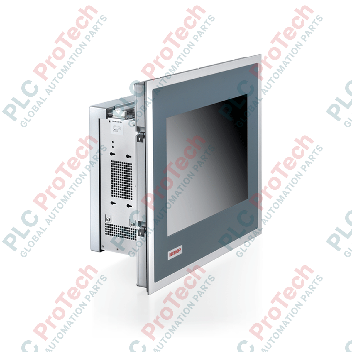
Designed to meet the stringent visualization and processing requirements of modern industrial environments, the Beckhoff CP6523-0002-0080 functions as a high-performance built-in Panel PC. This robust unit integrates a 19-inch active matrix TFT display within a industrial-grade ATX housing. Designed for seamless control cabinet installation, it combines the utility of an operator interface with the processing power required for real-time automation control. Its rugged mechanical design features front-side protection alongside toolless clamping installations, making it an optimal selection for complex machinery and process visual systems.
Features
-
High-Resolution Display: 19-inch TFT screen with a 1280 x 1024 pixel display resolution for clear interface visualization.
-
Rugged Front Construction: IP65-rated front panel protects the internal components from dust ingress and direct water contact.
-
Efficient Mounting Design: Pull-out clamping levers ensure swift, secure installation into control cabinets without loose parts.
-
Expandable Architecture: Built on a standard ATX motherboard configuration supporting multiple PCIe and PCI slots for network and communication cards.
-
Versatile Connectivity: Includes high-speed USB 3.0, dual DVI, DisplayPort, and RS232 interfaces for industrial peripheral integration.
Applications
-
Automotive Assembly Lines: Serves as the primary control and visual monitoring interface for complex robotic cells.
-
Chemical Processing Plants: Ideal for visual control panel deployment where high front-side dust and splash protection is mandatory.
-
Heavy Machinery Control: Integrates directly into machine frames to provide operators with processing statistics and diagnostics.
Technical Specifications
| Specification Parameter |
Technical Value |
| Manufacturer |
Beckhoff |
| Model Number |
CP6523-0002-0080 |
| Device Type |
Built-in Panel PC |
| Display Size |
19-inch Active Matrix TFT |
| Resolution |
1280 x 1024 Pixels |
| Protection Rating |
Front side IP65, Rear side IP20 |
| Operating Temperature |
0 to 55 degC |
| Motherboard Form Factor |
ATX Housing (7 Slots) |
| Ethernet Ports |
2 x 100/1000BASE-T on-board |
| USB Ports |
4 x USB 3.0 (Additional rear USB 2.0 supported) |
| Video Outputs |
2 x DVI, 1 x DisplayPort |
| Shipping Weight |
10.00 kg |
Connections and Interfaces
| Port / Connection Type |
Functional Assignment |
| RJ45 Ethernet (x2) |
Dual independent gigabit LAN ports for EtherCAT and local area network connectivity. |
| USB 3.0 (x4) |
High-speed connection for software updates, keypads, and diagnostic memory units. |
| DVI & DisplayPort |
External secondary display support for multi-monitor visualization. |
| RS232 Serial Port |
Legacy system link or dedicated serial barcode reader and scanner integration. |
Empirical Engineering Insights
Alternative Models & Compatibility
The CP6523 series features backward compatibility in mounting dimensions compared to legacy CP65xx-0001 configurations. However, transition plans must account for specific software platform updates. Due to the newer chipset on the -0080 suffix ATX motherboard, older Windows Embedded installations or TwinCAT 2 runtime systems may require driver updates or migration to TwinCAT 3 to function efficiently without peripheral communication delays.
Application Pitfalls & Engineering Notes
While the front display maintains an IP65 rating, the rear ATX housing is open-vented with an IP20 rating. If deploying this unit in environments with airborne particulates or high moisture, ensure the mounting cabinet has a dedicated cooling system or air-conditioning unit. Dust accumulation inside the 7-slot ATX chassis will impede CPU heat sink efficiency and may lead to protective thermal throttling at cabinet temperatures above 50 degC.
Commissioning & Wiring Tips
Always establish a dedicated low-impedance ground connection directly from the PE grounding bolt on the panel chassis to the cabinet backplate. When connecting high-resolution communication cables, route external DisplayPort or high-speed USB lines away from AC servo motor cables. This prevents high-frequency electromagnetic interference from corrupting the local display matrix or causing unexpected communication dropouts on the main bus.
Installation Guidelines
CRITICAL WARNING: Prior to attempting installation, servicing, or terminal wiring of this equipment, ensure all incoming power connections are completely de-energized. Allow a minimum of three minutes for residual capacitive charges within the internal power supplies to bleed off. Failure to comply can result in severe electrical shock, system damage, or firmware corruption.
-
1
Verify the cabinet cutout dimensions match the specifications for a 19-inch CP65xx series housing prior to insertion.
-
2
Ensure the circumferential rubber sealing gasket on the rear of the front panel is correctly seated and free of tears.
-
3
Insert the unit into the cutout and secure it in place by extending the integrated pull-out clamping levers. Tighten the levers evenly to compress the front gasket.
-
4
Connect the functional ground screw to the central cabinet earth bar. Secure all signal cables, power terminal blocks, and peripheral connections before energizing the circuit.