Description
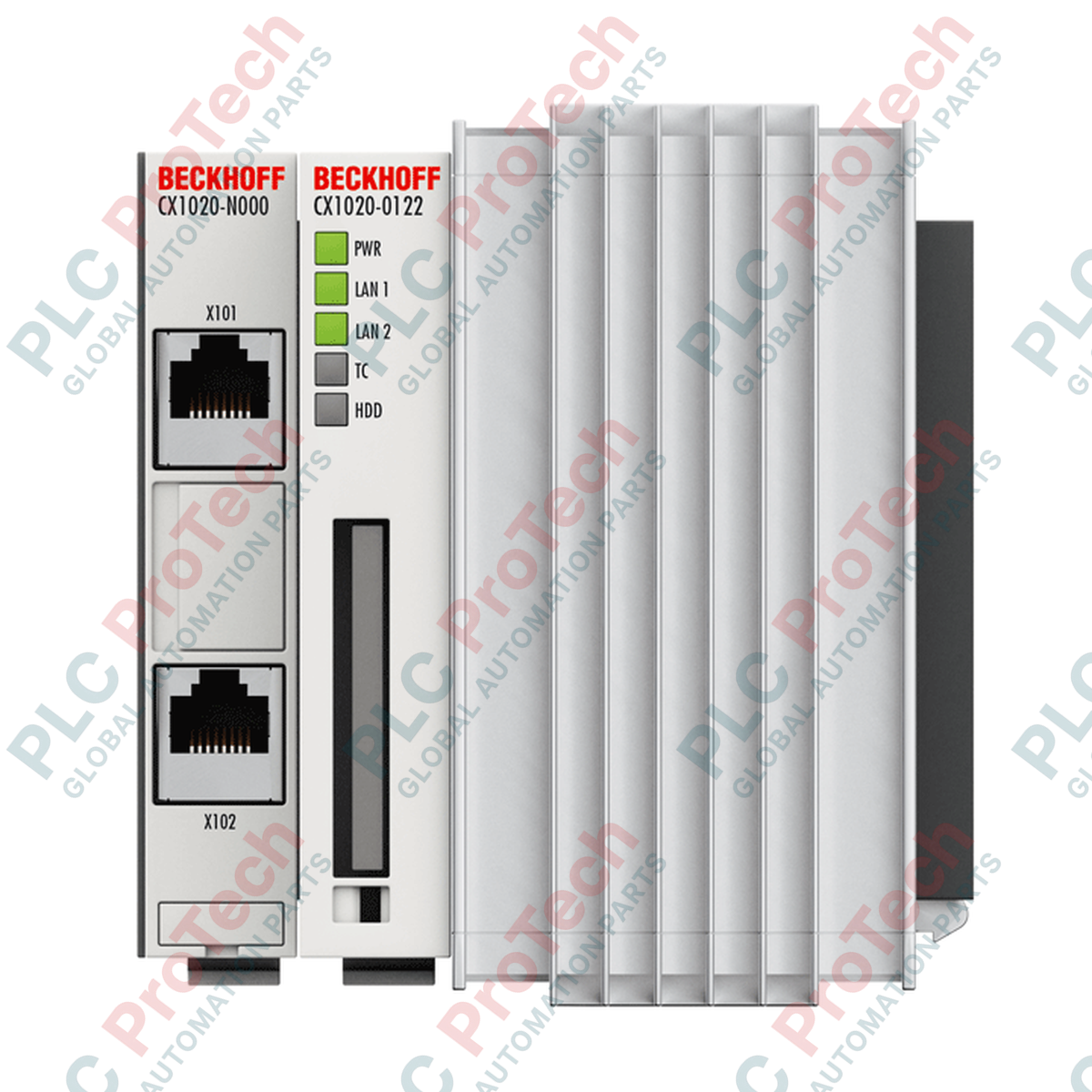
Executing complex automation tasks requiring dedicated industrial performance, the Beckhoff CX1020-0123 acts as the central execution engine of the modular CX control system. Driven by an Intel Celeron M ULV processor operating at a stable 1 GHz clock frequency, this embedded controller delivers high-speed deterministic control and connectivity in a compact, DIN-rail mounted footprint. The unit is optimized for integrated PC-based control, featuring an execution architecture designed directly for TwinCAT 2 NC I environments. Complete with dual Ethernet RJ45 ports and modular expansion interfaces, this Basic CPU Module ensures seamless integration with standard Beckhoff I/O terminals and power delivery units.
Features
-
Intel Celeron M Processor: Ultra-Low Voltage (ULV) processor architecture running at 1 GHz for fanless, energy-efficient operation.
-
Modular Memory Configuration: Features 256 MB of high-speed DDR RAM alongside a dedicated external Compact Flash Type I+II slot with eject mechanism.
-
Dual Ethernet Routing: Outfitted with 2 x RJ45 10/100 Mbit/s ports connected via an internal switch for linear or star physical network topologies.
-
TwinCAT Integration: Factory pre-installed with Windows Embedded Standard 2009 supporting the TwinCAT 2 NC I runtime for coordinated point-to-point motion execution.
-
Flexible I/O Interface: Connects to Beckhoff E-bus or K-bus I/O systems dynamically through compatible CX1100-xxxx series power supply modules.
Applications
- Multi-axis coordinated motion control and packaging machinery.
- Centralized plant automation systems requiring deterministic EtherCAT execution.
- Embedded visualization, human-machine interface (HMI), and data gateway applications.
- Test benches and laboratory automation setups requiring sub-millisecond task times.
Technical Specifications
| Parameter |
Value |
| Manufacturer |
Beckhoff Automation |
| Model / Article Number |
CX1020-0123 |
| Processor Type |
Intel Celeron M ULV (1 GHz, 1 Core) |
| Main Memory |
256 MB DDR RAM (expandable) |
| Flash Memory |
Compact Flash Slot (128 MB CF card included) |
| Interfaces |
2 x RJ45 10/100 Mbit/s (internal switch) |
| Diagnostics |
Power, LAN link/activity, TC status, flash access |
| Expansion Slot |
1 x Compact Flash Type I + II with eject mechanism |
| System Bus Connection |
16-bit ISA (PC/104) |
| Operating System |
Windows Embedded Standard 2009 |
| Control Software |
TwinCAT 2 NC I runtime |
| Power Supply |
Via system bus (through external CX1100-xxxx module) |
| Max. Power Consumption |
11 W |
| Dimensions (W x H x D) |
96 mm x 112 mm x 99 mm |
| Operating Temperature |
0 to +50 degC (no condensation) |
| Storage Temperature |
-25 to +85 degC |
| Vibration/Shock Resistance |
Conforms to EN 60068-2-6 / EN 60068-2-27 |
| Protection Rating |
IP20 |
| Net Weight |
550 g |
| Shipping Weight (Calculated) |
2.0 kg |
Connections and Interfaces
| Port / Interface |
Type |
Function Assignment |
| LAN 1 (X101) |
RJ45 (10/100 Mbit/s) |
Industrial Ethernet / TwinCAT Real-time communication (Port 1) |
| LAN 2 (X102) |
RJ45 (10/100 Mbit/s) |
Industrial Ethernet / TwinCAT Real-time communication (Port 2) |
| Compact Flash Slot |
CF Type I+II Insert |
System drive storage / Non-volatile registry and application file storage |
| System Bus (Right Side) |
16-Bit PC/104 ISA |
Direct communication and power bus link to CX1100 power supply module |
Alternative Models & Compatibility
The CX1020-0123 CPU module requires a corresponding power supply module from the CX1100 series (e.g., CX1100-0001 for K-bus or CX1100-0003 for E-bus/EtherCAT terminals) for direct bus communication. Replacing older, non-switch Ethernet CX series models requires updating system configurations within TwinCAT. Note that the memory options (256 MB vs. 1 GB) and OS variant (Windows Embedded Standard 2009 vs. Windows CE) must be matched carefully if migrating existing control programs to prevent execution faults.
Application Pitfalls & Engineering Notes
This system relies on convective cooling. Horizontal mounting is strictly forbidden as it disrupts thermal airflow, leading to localized heating and automatic hardware thermal throttling. When designing control cabinets, verify that at least 30 mm of free spatial clearance is left above and below the CX module. To ensure flash memory longevity, always enable the Enhanced Write Filter (EWF) or File-Based Write Filter (FBWF) within the OS to redirect unnecessary log-writes away from the Compact Flash card.
Commissioning & Wiring Tips
Before powering up the system for the first time, ensure the Compact Flash card is firmly seated with its locking mechanism closed. Do not hot-swap or eject the card while the green disk-access LED is lit, as this can result in total system drive corruption. Always complete physical bus configurations (connecting K-bus or E-bus terminals) when the entire rack is fully de-energized.
Installation Guidelines
CRITICAL WARNING
Disconnect all power sources and verify that no residual voltage remains on the system bus before installing or removing modules. Failure to de-energize the assembly can cause permanent electrical damage to the PC/104 system bus, the main CPU, and connected I/O terminals.
1
Mount the CX1020-0123 CPU module onto a standard 35 mm DIN rail (EN 60715) with vertical orientation.
2
Push the CPU module firmly to the left along the rail to lock its integrated PC/104 system bus connector into the adjacent CX1100 power supply module.
3
Insert the formatted Compact Flash card into the dedicated front expansion slot, ensuring it snaps securely into place.
4
Connect network and communication lines to the RJ45 interfaces, ensuring proper shield grounding on the cables.