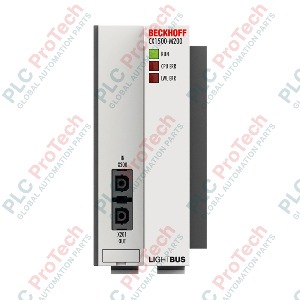
Description
Designed for seamless integration within modular industrial control environments, the Beckhoff CX1500-M200 fieldbus master connection establishes high-speed Lightbus communications directly from a compatible CX-series CPU. By utilizing fiber optic physical layers, this interface module guarantees complete electrical isolation and exceptional noise immunity across distributed field systems. The integration with the host controller is achieved through a high-bandwidth 2 kbytes DPRAM interface over an ISA plug-and-play architecture, ensuring rapid cyclic data exchanges. Perfect for synchronized motion and distributed I/O systems, the device supports both free-running and synchronized process data communication modes depending on the application requirements.
Features
-
High-Speed Transmission: Supports a fixed 2.5 Mbaud data transfer rate, capable of cycling 32 bits of process data in 25 microseconds.
-
Fiber Optic Physical Layer: Equipped with dual fiber optic interfaces to prevent electromagnetic interference and ground loops.
-
Large Network Capacity: Manages up to 254 distinct nodes with an aggregate capacity of up to 65,280 industrial I/O points.
-
TwinCAT Integration: Direct hardware driver compatibility with the TwinCAT 2 software platform for simplified system configuration.
-
Industrial Durability: Robust IP20 enclosure rated to withstand harsh mechanical vibration and thermal environments.
Applications
- High-speed multi-axis motion synchronization over fiber optic rings.
- Industrial manufacturing plants with severe electromagnetic noise and interference.
- Distributed telemetry systems and high-density I/O networking over extended distances.
- Legacy machine retrofits and maintenance of TwinCAT 2 control architectures.
Technical Specifications
| Parameter |
Specification Value |
| Manufacturer |
Beckhoff |
| Model / Article Number |
CX1500-M200 |
| Fieldbus System |
Lightbus |
| Data Transfer Rate |
2.5 Mbaud |
| Process Data Cycle Time |
32 bits in 25 microseconds |
| Bus Interface |
2 x fiber optic ports |
| Maximum Nodes |
254 nodes (max. 65,280 I/O points) |
| CPU Interface |
ISA plug and play, 2 kbytes DPRAM |
| Max. Power Loss |
2 W |
| Operating Temperature |
0 to +55 degC |
| Storage Temperature |
-25 to +85 degC |
| Relative Humidity |
95%, non-condensing |
| Protection Rating |
IP20 |
| Driver Support |
Compatible only with TwinCAT 2 |
| Vibration/Shock Resistance |
Conforms to EN 60068-2-6 / EN 60068-2-27 |
| EMC Immunity/Emission |
Conforms to EN 61000-6-2 / EN 61000-6-4 |
| Approvals |
CE, UL |
| Dimensions (W x H x D) |
38 mm x 100 mm x 91 mm |
| Net Weight |
190 g |
| Shipping Weight (Calculated) |
2.0 kg |
Connections and Interfaces
| Port / Interface Type |
Function / Assignment |
| Optical Port 1 (Tx) |
Lightbus optical transmitter connection to the ring network. |
| Optical Port 2 (Rx) |
Lightbus optical receiver connection completing the ring loop. |
| Backplane Interface |
Integrated PC104/ISA Bus for physical connection and power distribution from the CX CPU. |
Empirical Engineering Insights
Alternative Models & Compatibility
The CX1500-M200 is designed exclusively for CX-series hardware configurations operating under TwinCAT 2 runtimes. It cannot be mapped or configured under TwinCAT 3 due to the hardware-level dependencies of the legacy ISA DPRAM address space. Ensure your system CPU supports PC104 expansion channels before engineering replacements.
Application Pitfalls & Engineering Notes
When laying optical fiber cables for the Lightbus loop, strictly adhere to the manufacturer's specified minimum bending radius. Kinking or over-bending the optical fibers causes critical light signal attenuation, leading to intermittent cyclic redundancy check (CRC) errors or complete bus synchronization failures.
Commissioning & Wiring Tips
Always power down the control stack before cleaning or inserting optical fiber connectors. Dust ingress within the active physical transceivers can permanently degrade light output. Prior to initial startup, verify the mechanical alignment of the CPU extension connector to avoid bent pins on the backplane.
Installation Guidelines
CRITICAL WARNING:
Isolate and lock out all power sources feeding the host controller and connected field devices before initiating module insertion or removal. Failing to perform total system de-energization may damage the sensitive DPRAM physical layer of the host CPU and invalidate your warranty.
1
Power down the main control cabinet and verify that no residual energy remains in any auxiliary supply lines.
2
Mount the module directly onto the standard DIN rail (TS35), sliding it towards the host CX controller stack until the backplane contacts engage firmly.
3
Secure the stack by snapping end brackets on both sides of the assembled system to prevent side-to-side drift or mechanical disconnection.
4
Connect the incoming and outgoing fiber optic cables, confirming that the Tx (transmit) line connects to the corresponding Rx (receive) port of the adjacent field node.