Description
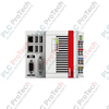
Providing extended local system expansion directly from the CX2000 Embedded PC series, the Beckhoff CX2550-0179 functions as a high-reliability transmitter module for USB signals. This unit transmits USB 1.1 data packets over extensive plant floor runs, facilitating a secure link between the central processor and a remote operator interface such as the CP69xx-xxxx-0000 series control panels. By utilizing the proprietary USB Extended technology, it eliminates the need for active signal repeaters while maintaining deterministic communication.
Key Features
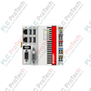
- Direct physical and electrical integration with the left-side system connection of CX20xx Embedded PCs.
- Transmission of USB 1.1 signals up to a maximum distance of 50 meters.
- Utilizes standard, cost-effective Cat.5E shielded twisted-pair cabling for physical transport.
- Integrated RJ45 connection socket designed for high mechanical retention in high-vibration panels.
- Zero-configuration operation via system bus power routing, requiring no external power supply wiring.
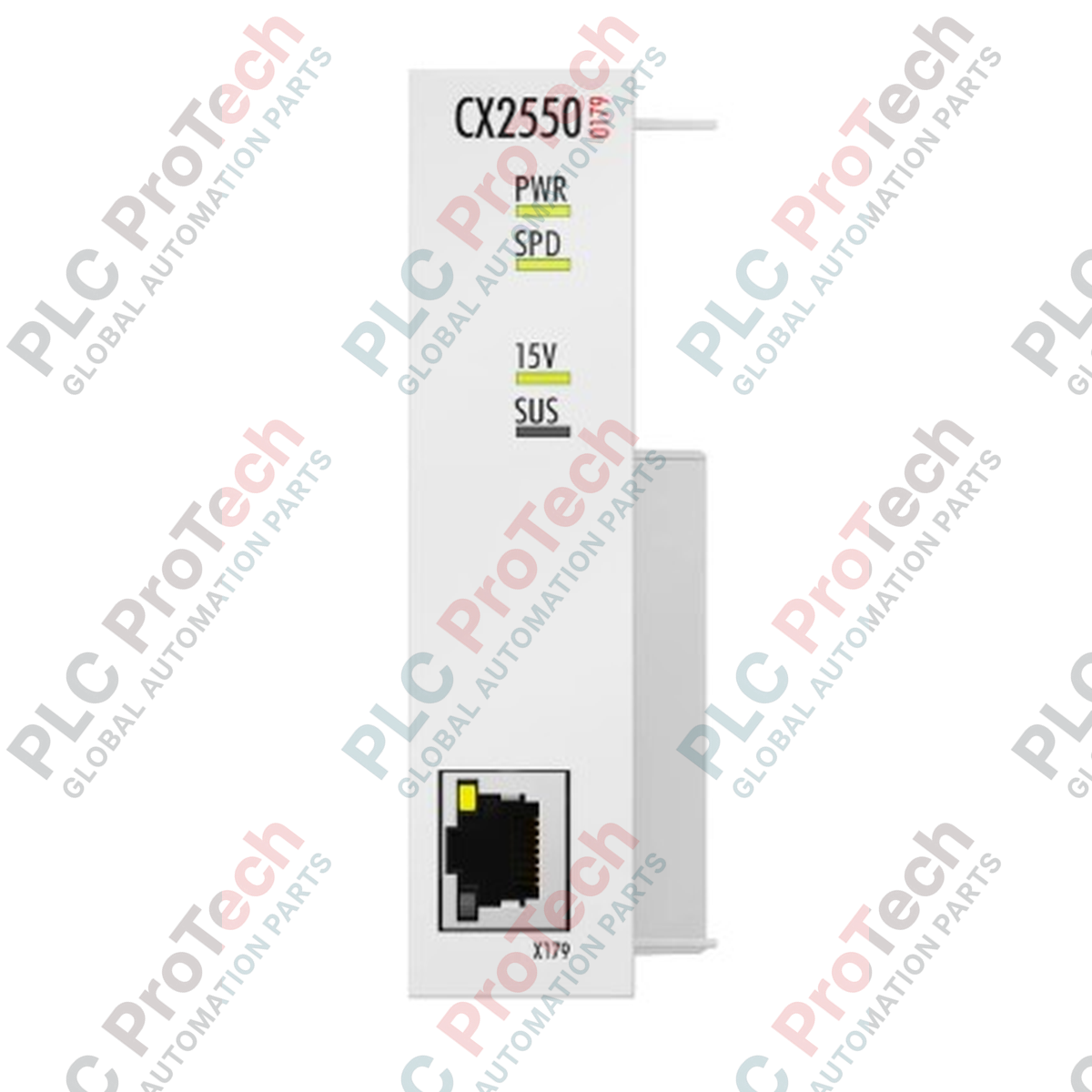
- Four diagnostic LEDs providing direct status visibility for Power, Speed, +15 V, and Suspend states.
Applications
- Decentralized visualization panels (CP69xx-xxxx-0000) mounted on machine swing arms.
- Remote human-machine interfaces (HMI) located away from high-noise electrical cabinets.
- Long-range peripheral configuration and diagnostic ports in assembly lines.
Technical Specifications
| Specification Parameter |
Value / Details |
| Manufacturer |
Beckhoff Automation |
| Model Number |
CX2550-0179 |
| Interface Type |
1 x USB Extended 1.1 Transmitter |
| Physical Connection |
RJ45 Shielded Socket |
| Transmission Distance |
Max. 50 m via Cat.5E cable |
| Power Supply |
Via system bus (powered through CX2100-0xxx power supply modules) |
| LED Diagnostics |
1 x Power, 1 x Speed, 1 x +15 V, 1 x Suspend |
| Operating Temperature |
-25 to +60 degC |
| Storage Temperature |
-40 to +85 degC |
| Relative Humidity |
95%, non-condensing |
| Protection Rating |
IP20 |
| Dimensions (W x H x D) |
24 mm x 99 mm x 54.5 mm |
| Net Weight |
190 g |
| Vibration/Shock Resistance |
Conforms to EN 60068-2-6 / EN 60068-2-27 |
| EMC Immunity/Emission |
Conforms to EN 61000-6-2 / EN 61000-6-4 |
Empirical Engineering Insights
Alternative Models & Compatibility
The CX2550-0179 is designed exclusively as a USB 1.1 transmitter. If your target peripheral or remote HMI requires USB 2.0 speeds (e.g., for external storage, heavy file transfers, or modern touch controllers requiring USB 2.0 bandwidth), the CX2550-0079 should be used instead. Note that the transmitter module must always match the capability of the receiver card built into the CP69xx control panel series.
Application Pitfalls & Engineering Notes
When calculating thermal dissipation inside compact, unventilated electrical cabinets, factor in the 190 g modules continuous heat output alongside the main CX CPU module. To ensure consistent signal integrity, avoid parallel routing of the Cat.5E connection cable with high-voltage AC motor drives or heavy contactor supply lines. While the unit complies with EN 61000-6-2 industrial immunity standards, severe electromagnetic fields can trigger transient packet drops, causing the 'Suspend' LED to toggle.
Commissioning & Wiring Tips
Always utilize STP (Shielded Twisted Pair) Cat.5E cabling with fully metal-shielded RJ45 plugs. Ensure the metal shielding on the cable makes direct contact with the grounding shroud of the RJ45 socket on both the CX2550-0179 transmitter and the receiver unit. If the grounding path is compromised, electrostatic build-up may cause communication interruptions or require a cold reboot of the CX20xx controller.
Installation Guidelines
CRITICAL WARNING:
Do not install or remove the CX2550-0179 transmitter module while the central control system is powered. Ensure the primary CX2100-0xxx power supply module is completely de-energized and wait at least 30 seconds for all residual capacitance to bleed down before mechanical mounting. Failure to comply can result in permanent damage to the multi-pin PC/104 system bus interface.
1
Disconnect all power from the main control panel and verify that the system is safe to touch.
2
Align the CX2550-0179 guide pins with the left-hand expansion connector of the CX20xx CPU module.
3
Press the two units together gently until the locking mechanism fully clicks, verifying a gap-free fit.
4
Insert the shielded Cat.5E patch cable into the RJ45 port until it locks in place, ensuring the cable strain relief is secure.
5
Re-energize the power supply module. Confirm the Power and diagnostic LEDs light up, indicating communication initialization with the TwinCAT platform.