Description
Directly capturing 16 digital sensor signals from the field, the Beckhoff ERI1809-0022 distributes decentralized I/O data through an integrated IO-Link interface. Built with a robust zinc die-cast housing, this module offers superior mechanical resilience and shielding compared to standard plastic housings, making it suitable for wet, high-vibration, and demanding industrial environments. The device operates as an IO-Link Class A device, transmitting input states to any compatible IO-Link master via a high-speed COM3 interface.
Features
-
16 Digital Inputs: High-density sensor integration in a single field-mounted block.
-
Zinc Die-Cast Housing: Enhanced mechanical protection, impact resistance, and electromagnetic shielding.
-
IO-Link COM3 Interface: Supports high-speed data transfer rates up to 230.4 kbaud.
-
Adjustable Input Filter: Configurable input filtering from 0 to 20 ms (3 ms default) to prevent signal bounce.
-
Type 3 Input Characteristics: Conforms to EN 61131-2 Type 3 standards, optimizing current draw for modern electronic sensors.
-
IP67 Rated Protection: Fully sealed against dust and water immersion, designed for direct machine mounting without an enclosure.
Applications
-
Decentralized Conveyor Systems: Distributed sensor gathering across extensive logistics layouts.
-
Automotive Assembly Lines: Rugged, weld-spatter-resistant installations requiring high-density digital feedback.
-
Packaging Machinery: Compact field wiring to eliminate centralized junction boxes.
-
Machine Tooling: Wet environments where coolant and metal chips are present.
Technical Specifications
| Parameter |
Value |
| Manufacturer |
Beckhoff |
| Model |
ERI1809-0022 |
| Communication Protocol |
IO-Link V1.1, Class A |
| Data Transfer Rate |
230.4 kbaud (COM3) |
| Number of Inputs |
16 digital inputs |
| Input Voltage Range |
24 V DC (-15 percent / +20 percent) |
| Signal Voltage "0" |
-3 to +5 V DC (EN 61131-2, Type 3) |
| Signal Voltage "1" |
11 to 30 V DC (EN 61131-2, Type 3) |
| Input Filter Config |
3.0 ms default (adjustable 0 to 20 ms) |
| Current Consumption |
Typically 100 mA from L+ |
| Sensor Supply |
Max. 0.5 A from L+, short-circuit proof |
| Housing Material |
Zinc die-cast |
| Protection Rating |
IP65 / IP66 / IP67 (conforms to EN 60529) |
| Operating Temperature |
-25 to +60 degC |
| Storage Temperature |
-40 to +85 degC |
| Dimensions (W x H x D) |
60 mm x 126 mm x 26.5 mm |
| Net Weight |
450 g |
| Shipping Weight (Calculated) |
0.65 kg |
| Country of Origin |
Germany |
Connections and Interfaces
| Interface / Port |
Connector Type |
Assignment / Function |
| IO-Link Connection |
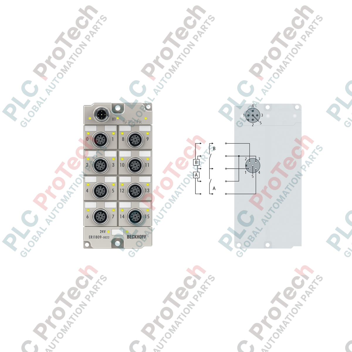
1 x M12 plug, A-coded |
L+ (24V DC), L- (0V), IO-Link C/Q line |
| Digital Inputs (1-16) |
8 x M12 sockets (2 inputs per port) |
Pin 4: Input A, Pin 2: Input B, Pin 1: +24 V DC supply, Pin 3: 0 V GND |
Empirical Engineering Insights
Alternative Models & Compatibility
The ERI1809-0022 is the direct zinc die-cast equivalent of the plastic-housed EP1809-0022. Both modules share identical electrical specifications, pin configurations, and firmware registers. If replacing an EP module, the ERI offers identical mount spacing, but features a thicker profile. Ensure adequate depth clearances within your mechanical footprint.
Application Pitfalls & Engineering Notes
Because this is an IO-Link Class A module, both the unit's internal logic and the connected sensor field power are drawn entirely from the primary L+ and L- lines of the IO-Link master port. The total available sensor supply is limited to 0.5 A. Connecting power-hungry inductive sensors or high-current photoeyes can cause the internal short-circuit protection to trip. For configurations exceeding 500 mA, consider utilizing an IO-Link Class B module or an auxiliary power supply distribution block.
Commissioning & Wiring Tips
By default, the digital inputs are configured with a 3.0 ms hardware filter. While effective for typical proximity switches, high-speed applications (such as rotary encoders or flow pulse meters) will require updating the parameter index via the TwinCAT System Manager (or other IO-Link configuration tools) to 0.0 ms. Always utilize shielded M12 cables for runs exceeding 10 meters to prevent high-frequency noise interference from adjacent variable frequency drives.
Installation Guidelines
CRITICAL WARNING: Ensure the entire IO-Link master assembly is fully de-energized before mounting or routing cabling. Never hot-plug M12 input or communication connections while field power is active to prevent transient arcs and potential damage to internal IO-Link transceiver ICs.
1
Mount the zinc die-cast housing directly onto a flat, vibration-resistant surface using two M3 screws (3.5 mm holes) or two M4 screws (4.5 mm holes).
2
Connect the primary IO-Link interface using a standard A-coded, shielded M12 cable, ensuring the lock nuts are tightened to 0.6 Nm to maintain the IP67 seal integrity.
3
Map the sensor inputs to the corresponding M12 sockets. Cap any unused sockets with IP67 protective plugs to prevent moisture intrusion.