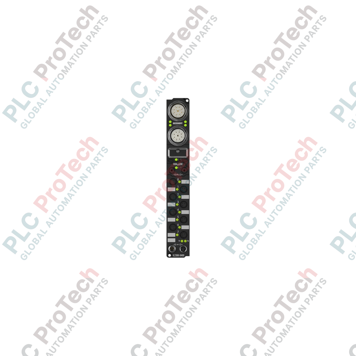
Description
Designed to manage high-speed industrial communications within rugged environments, the Beckhoff IL2300-B400 establishes a direct interface between the Lightbus system and decentralized IP67 Extension Box modules. This coupler box allows for efficient modular expansion directly on the machinery, eliminating the need for protective control cabinets. By converting Lightbus telegrams into the internal Extension Box protocol, the device ensures near-instantaneous I/O updates. Its robust construction guarantees superior mechanical stability, making it highly reliable in demanding manufacturing and process automation layouts.
Features
- Supports up to 120 decentralized extension modules for flexible system scalability.
- Handles up to 512 digital inputs and 512 digital outputs per fieldbus node.
- Manages up to 28 analog inputs and 28 analog outputs for complex instrumentation integration.
- Full configuration, commissioning, and parameter setting via the KS2000 software tool.
- Heavy-duty M23 and M8 connections engineered for severe industrial environments.
Applications
- Cabinet-free, decentralized machine control architectures.
- Automotive assembly lines utilizing high-speed Lightbus configurations.
- Material handling and packaging equipment requiring dense distributed I/O points.
- Wet or dusty environments requiring IP67 ingress protection.
Technical Specifications
| Parameter |
Value / Specification |
| Manufacturer |
Beckhoff |
| Model Number |
IL2300-B400 |
| Fieldbus Protocol |
Lightbus |
| Max Extension Modules |
120 (max. 64 byte input / 64 byte output data) |
| Digital Peripherals Capacity |
Max. 512 inputs and 512 outputs |
| Analog Peripherals Capacity |
Max. 28 inputs and 28 outputs |
| Configuration Interface |
Via KS2000 software |
| Bus Connection Ports |
1 x M23 female 9-pin socket, 1 x M23 male 9-pin socket |
| Power Supply (Control) |
24 V DC (Permissible range: 20 to 29 V DC) |
| Power Supply (Load) |
Determined by connected Extension Box I/O types |
| Power Feed Interface |
1 x M8 male socket, 4-pin |
| Downstream Power Interface |
1 x M8 female socket, 4-pin |
| Current Consumption (Box Supply) |
85 mA + sensor loads (max. 0.5 A total) |
| Electrical Isolation |
Control voltage/fieldbus: None; Control voltage/I/O: By I/O type |
| Ingress Protection Rating |
IP65 / IP66 / IP67 (conforms to EN 60529) |
| Operating Temperature |
0 to +55 degC |
| Storage Temperature |
-25 to +85 degC |
| Vibration/Shock Resistance |
Conforms to EN 60068-2-6 / EN 60068-2-27 |
| EMC Immunity/Emission |
Conforms to EN 61000-6-2 / EN 61000-6-4 |
| Net Unit Weight |
350 g |
| Shipping Weight (Calculated) |
2.0 kg |
Connections and Interfaces
| Connector Type |
Pin Configuration |
Functional Assignment |
| M23 Fieldbus In |
9-pin Female Socket |
Incoming Lightbus signals and diagnostic feedback loop |
| M23 Fieldbus Out |
9-pin Male Socket |
Downstream Lightbus extension to adjacent field nodes |
| M8 Power Input |
4-pin Male (Feed) |
Pin 1: +24 V DC Control; Pin 2: +24 V DC Load; Pin 3: GND Control; Pin 4: GND Load |
| M8 Power Output |
4-pin Female (Downstream) |
Loop-through control and load voltages to next Extension Box |
Alternative Models & Compatibility
The IL2300-B400 is specifically dedicated to Beckhoff Lightbus architectures. If your installation requires transition to alternative fieldbus networks, the Beckhoff IP67 Fieldbus Box range features alternative options, such as the IL2300-B310 (PROFIBUS) or the IL2300-B510 (CANopen). For modern Industrial Ethernet networks, migrate to the EtherCAT EP series modules. Note that configuration files and mapping configurations compiled in KS2000 for Lightbus cannot be migrated directly to other protocols without hardware profile reconfiguration.
Application Pitfalls & Engineering Notes
To maintain the specified IP67 protection rating, all unused M23 and M8 connectors must be sealed using industrial-grade protective caps. The internal box supply current is limited to 0.5 A for connected sensors. In applications where sensors require higher current draws, run auxiliary external power lines rather than powering directly through the module. Pay close attention to the bend radius of the Lightbus fiber optic cables; tight bends can lead to data attenuation and intermittent fieldbus communication drops.
Commissioning & Wiring Tips
When connecting the device, use separate wire routing for control voltage and high-current AC lines to prevent electromagnetic coupling. Use shielded M23 and M8 cables for communication lines to preserve signal integrity against high-frequency noise. During initial software configuration in KS2000, ensure the hardware addresses mapped in your PLC config tool match the physical physical nodes in sequence, particularly when managing maximum I/O extension counts.
Installation Guidelines
CRITICAL WARNING:
Ensure all control and load power supplies are fully disconnected before beginning installation, wiring modifications, or maintenance. High transient voltages or sudden machine activation during installation may cause electrical shock or severe damage to sensitive electronic components.
1
Mount the coupler module securely to the machinery frame using the integrated mounting holes. Ensure the installation surface is flat to prevent torque stress on the housing.
2
Connect the incoming Lightbus fiber optic lines to the M23 female input socket and the downstream loop to the M23 male socket. Fully hand-tighten the coupling rings.
3
Attach the M8 4-pin feed cable to supply the 24 V DC control and load voltages. If cascading power to further Extension Boxes, connect the M8 downstream cable.
4
Fit heavy-duty dust caps onto any open or unused M8 or M23 ports to ensure watertight performance. Perform software diagnostics via KS2000 prior to machine commissioning.