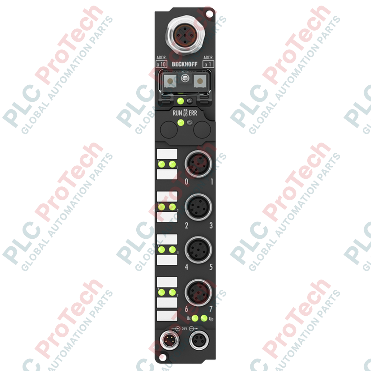
Description
Decentralized signal acquisition on machine frames and production lines is executed reliably by the Beckhoff IP1002-B810 Fieldbus Box. This device gathers binary control signals from up to eight digital sensors and transmits them over a point-to-point RS232 interface to the master controller. Housed in a robust, fully-sealed polyamide shell, the IP1002-B810 does not require a protective sub-cabinet, enabling direct machine-mount installation in heavy industrial settings. Key features include an integrated 3.0 ms input filter to prevent contact bounce and standard M12 screw-type connection points for rugged sensor field-wiring.
Features
-
8 Digital Inputs: Supports direct connection of standard 24 V DC binary sensors.
-
RS232 Serial Interface: Peer-to-peer communication protocol with selectable data transfer rates up to 38.4 kbaud.
-
Rugged Sealed Housing: Highly durable PA6 polyamide design conforms to IP65, IP66, and IP67 protection classes.
-
Input Filtering: Integrated 3.0 ms hardware filter to suppress signal noise and contact chatter.
-
Flexible Mounting: Two pre-drilled 3.5 mm structural fixing holes for direct M3 screw attachment to machinery.
Applications
- Distributed packaging machine automation systems.
- Conveyor and material handling control networks.
- Wet process areas requiring high ingress protection ratings.
- Dedicated serial peer-to-peer data logging configurations.
Technical Specifications Table
| Parameter |
Specification |
| Manufacturer |
Beckhoff Automation |
| Model Reference |
IP1002-B810 |
| Product Type |
Fieldbus Box Digital Input Module |
| Number of Inputs |
8 digital inputs |
| Interface Protocol |
RS232 (open, documented protocol) |
| Data Transfer Rates |
9.6 kbaud, 19.2 kbaud, 38.4 kbaud (default) |
| Nominal Input Voltage |
24 V DC (-15% / +20%) |
| "0" Signal Voltage |
-3 to +5 V (EN 61131-2, type 2) |
| "1" Signal Voltage |
11 to 30 V (EN 61131-2, type 2) |
| Input Filter Time |
3.0 ms |
| Box Current Consumption |
45 mA + sensor current (max 0.5 A total) |
| Power Supply Connections |
Feed: 1 x M8 male, 4-pin; Downstream: 1 x M8 female, 4-pin |
| Bus Interface Connection |
1 x M12 socket, 5-pin, B-coded |
| Sensor Connections |
M12, screw-type connection |
| Housing Material |
PA6 (Polyamide) |
| Ingress Protection Rating |
IP65, IP66, IP67 (conforms to EN 60529) |
| Operating Temperature Range |
0 to +55 degC |
| Storage Temperature Range |
-25 to +85 degC |
| Approvals |
CE, UL |
| Dimensions (W x H x D) |
30 mm x 175 mm x 26.5 mm |
| Net Weight |
Approx. 210 g |
| Shipping Weight (Calculated) |
2.0 kg |
Connections and Interfaces
| Connector/Terminal |
Function / Pin Assignment |
| M8 Power Feed (Male) |
Pin 1: +24 V DC Control Voltage (US), Pin 2: +24 V DC Load Voltage (UP), Pin 3: GND (US), Pin 4: GND (UP) |
| M8 Downstream (Female) |
Daisy-chain connection to downstream modules (US, UP, GND US, GND UP) |
| M12 Bus Interface (B-coded) |
RS232 Serial communication lines (RXD, TXD, GND interface connections) |
Empirical Engineering Insights
Alternative Models & Compatibility
The IP1002-B810 model relies on a standard RS232 peer-to-peer connection, which is distinct from the fieldbus-specific IP1002 network modules (such as CANopen or PROFIBUS variants). When configuring the serial link, ensure the controller's serial port parameters match the module's default baud rate of 38.4 kbaud. Standard configuration tasks can be managed directly using Beckhoff's KS2000 software interface via the specified programming adapters.
Application Pitfalls & Engineering Notes
Because RS232 is an unbalanced communication interface, the maximum length of the serial connection cable is strictly limited to 15 meters. Exceeding this distance or using low-grade unshielded cables in high-interference environments (e.g., adjacent to variable frequency drives) will lead to transmission errors and module timeouts. Ensure that the total current draw of connected sensors does not exceed the short-circuit protected limit of 0.5 A across the module.
Commissioning & Wiring Tips
When routing the control cables, use shielded copper wiring (2 x 0.25 mm²) specifically rated for RS232 transmissions. Ensure the shield is grounded properly on the host controller side. For the M8 power distribution daisy chain, verify that the cumulative control voltage (US) draw of all downstream modules does not exceed the contact rating of the feed connectors, which is typically capped at 4 A.
Installation Guidelines
CRITICAL WARNING: Prior to mounting or performing any wiring work on the Fieldbus Box, ensure all power sources—both control voltage (US) and auxiliary load voltage (UP)—are fully de-energized. Failure to isolate power can result in terminal damage, sensor damage, or unexpected system state transitions.
1
Mechanical Mounting: Secure the IP1002-B810 to a flat machine surface using two M3 screws through the 3.5 mm diameter mounting holes. Tighten to the recommended torque spec for your mounting substrate.
2
RS232 Bus Connection: Insert the B-coded 5-pin M12 bus cable into the communication port. Hand-tighten the screw coupling to secure the IP67-rated seal.
3
Power Feed Integration: Connect the incoming 24 V DC power source to the 4-pin M8 male connector. If daisy-chaining, run an M8 cable from the female downstream port to the next fieldbus module.
4
I/O Sensor Termination: Connect the 8 digital sensors to the respective M12 peripheral connections. Seal all unused ports with M12 protective caps to prevent fluid ingress and maintain the IP67 rating.