Description
Engineered for high-speed pulse processing in decentralized automation setups, the Beckhoff IP1502-B800 serves as a robust 2-channel counter module within the Fieldbus Box architecture. This dust- and water-tight field I/O unit integrates two independent 32-bit counters capable of handling pulse frequencies up to 100 kHz, making it suitable for rotational speed measurement, length acquisition, and positioning tasks directly in harsh field environments. Utilizing an RS485 transmission medium, this device communicates via a documented open serial protocol, enabling reliable integration into distributed control systems without requiring an additional protective enclosure.
Features
-
Dual High-Speed Counters: Two independent 32-bit counters with a maximum input frequency of 100 kHz.
-
Versatile Inputs: Incorporates 2 counter inputs, 2 gate inputs, and 2 up/down switches for directional counting.
-
Integrated Outputs: Features 2 short-circuit-proof 24 V DC outputs rated at 0.5 A for direct actuator control.
-
Rugged Fieldbus Box Design: Fully encapsulated IP67-rated housing for direct on-machine mounting without control cabinets.
-
RS485 Communication: Uses shielded copper cabling supporting variable transmission speeds up to 38.4 kbaud over distances up to 1200 meters.
-
Flexible Configuration: Configurable parameters, parameters, and operation modes via the Beckhoff KS2000 software tool.
Applications
- High-speed pulse acquisition for industrial flowmeters and encoder tracking.
- Decentralized positioning and length measurement in woodworking and metalworking machinery.
- Rotational speed (RPM) monitoring in wind power plants and heavy-duty conveyor systems.
- In-line parts counting and packaging line synchronization.
Technical Specifications
| Parameter |
Specification Value |
| Manufacturer |
Beckhoff |
| Model Identifier |
IP1502-B800 |
| Fieldbus Interface |
RS485 (1 x M12 socket, 5-pin, B-coded) |
| Number of Counters |
2 (32-bit depth each) |
| Counting Frequency |
100 kHz (2 kHz for up/down switching) |
| Nominal Input Voltage |
24 V DC (-15% / +20%) |
| Signal Voltage Level |
"0" signal: -3 to +5 V | "1" signal: 11 to 30 V (EN 61131-2, type 2) |
| Digital Outputs |
2 x 24 V DC, 0.5 A (short-circuit proof) |
| Sensor Supply |
Derived from control voltage, max 0.5 A total, short-circuit proof |
| Power Connections |
Feed: M8 male, 4-pin; Downstream: M8 female, 4-pin |
| Current Consumption |
45 mA + sensor load (max 0.5 A) |
| Enclosure Rating |
IP65 / IP66 / IP67 (conforms to EN 60529) |
| Operating Temperature |
0 to +55 degC |
| Storage Temperature |
-25 to +85 degC |
| Dimensions (W x H x D) |
30 mm x 175 mm x 26.5 mm |
| Housing Material |
Polyamide PA6 |
| Net Weight |
approx. 210 g |
| Shipping Weight (Calculated) |
2.0 kg |
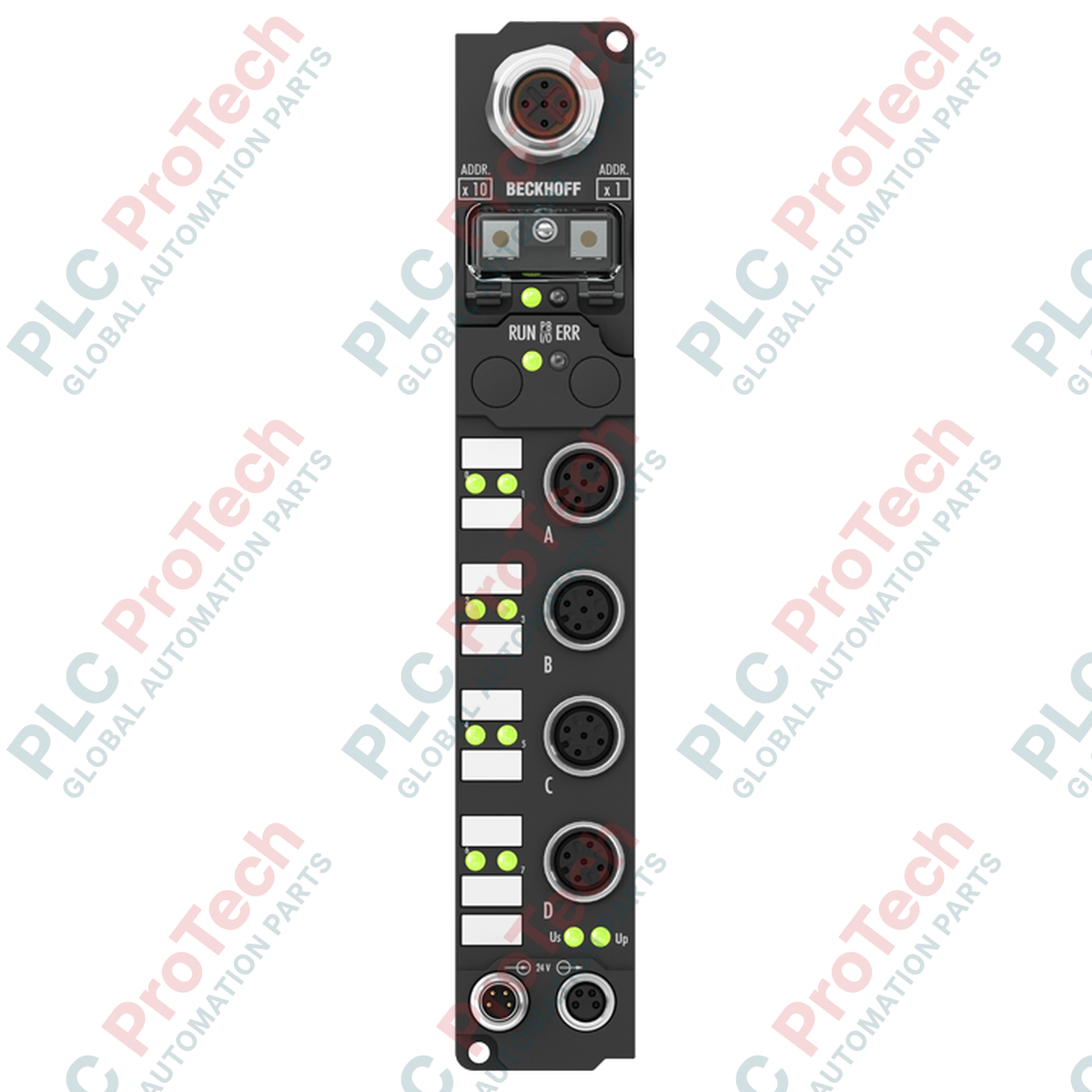
Connections and Interfaces
| Interface Connection |
Connector Type |
Function / Pin Mapping |
| Bus Interface |
1 x M12 socket, 5-pin, B-coded |
RS485 Serial Comm (RxD/TxD-A, RxD/TxD-B, GND, Shield) |
| Power Feed |
1 x M8 male, 4-pin |
24 V DC control voltage (Us), load voltage (Up), GNDs |
| Power Downstream |
1 x M8 female, 4-pin |
Feed-through loop-out for adjacent Fieldbus Boxes |
| Signal Connections |
M12 screw-type sockets |
Channel 1 & 2 inputs (counter, gate, up/down), auxiliary sensor supply, and digital outputs |
Empirical Engineering Insights
Alternative Models & Compatibility
The B800 series utilizes Beckhoff's proprietary RS485 serial fieldbus protocol. It is primarily compatible with serial coupling networks like the IPxxxx-B800 and IL230x-B800 couplers. If migrating to modern protocols such as EtherCAT or PROFINET, equivalent units from the EP series (such as the EP1518 or EP5101) should be evaluated. Ensure your master controller has the correct serial interface card configured to parse the 80-bit process image (comprising 2 x 32-bit counter values along with control/status words).
Application Pitfalls & Engineering Notes
When operating at the maximum frequency of 100 kHz, ensure that signal cabling is strictly shielded and kept separate from high-power motor lines. Standard M12 unshielded cables can pick up inductive noise, causing false pulse increments. Also note that up/down switching logic relies on a hardware signal that has a reduced frequency threshold of 2 kHz; attempting to toggle direction faster than this rate can lead to mismatched positional register counts.
Commissioning & Wiring Tips
Always configure the serial communication baud rate via the KS2000 software before deployment. The default baud rate is set to 38.4 kbaud. When daisy-chaining multiple boxes along the RS485 bus, a termination resistor (120 Ohm) must be placed at the final physical node on the network to prevent transmission reflections, especially over long cable runs exceeding 100 meters.
Installation Guidelines
CRITICAL WARNING
Disconnect all power sources (control voltage Us and load voltage Up) before installing or disconnecting M8 and M12 connectors. Operating connections under load can cause electrical arcing, damage high-sensitivity internal counter components, and compromise the unit's ingress protection.
1
Mount the Fieldbus Box using the 2 integrated 3.5 mm mounting holes with M3 hardware. Ensure the mounting surface is flat to prevent torque stress on the polyamide housing.
2
Tighten all mating M12 and M8 cable connectors to the specified torque values (0.6 Nm for M12, 0.4 Nm for M8) to guarantee an IP67 liquid-tight seal.
3
Apply 24 V DC to the M8 power feed port and verify status LEDs illuminate, confirming the internal control circuitry is active prior to initiating serial communication.