Description
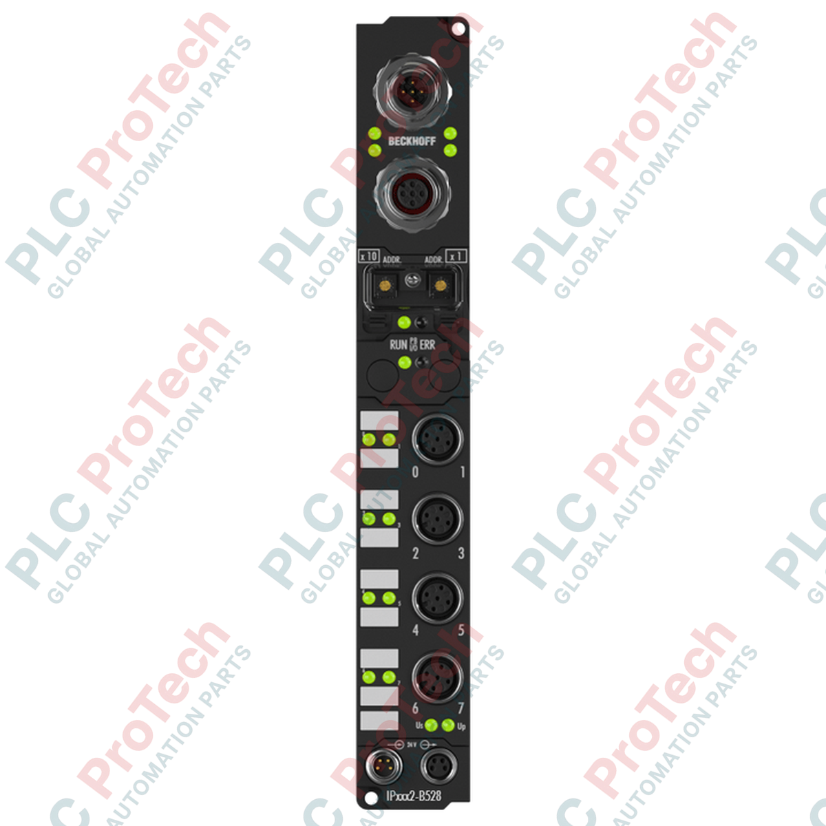
Designed to optimize decentralized control layouts, this Beckhoff IP2042-B528 digital output module enables high-capacity load switching directly on-machine via a DeviceNet fieldbus interface. By shifting the I/O layer out of the central control cabinet and directly onto the equipment frame, it minimizes wiring overhead and reduces signal degradation. The module features eight independent digital outputs designed to switch 24 V DC loads up to 2 A per channel, utilizing standard M12 screw-locking connectors to guarantee reliable signal delivery under harsh operating conditions.
Features
-
DeviceNet Fieldbus Integration: Built-in DeviceNet interface with an integrated T-connector simplifies bus cabling and allows direct network loop-through.
-
High-Capacity Outputs: Eight digital outputs capable of switching up to 2 A per channel, ideal for driving pneumatic valves, contactors, and actuators.
-
Secure Physical Connections: Industry-standard M12 connection interface ensures dust-tight, water-resistant, and vibration-proof wiring.
-
Optimized Form Factor: Machine-mountable design eliminates the requirement for local IP67 terminal boxes or extensive terminal strip wiring.
Applications
- Decentralized machine control systems and distributed manufacturing lines.
- Pneumatic manifold control and solenoid valve actuation.
- Conveyor networks and automated material handling equipment.
- High-vibration industrial environments requiring direct-on-machine I/O placement.
Technical Specifications
| Parameter |
Specification |
| Manufacturer |
Beckhoff |
| Model Number |
IP2042-B528 |
| Fieldbus Interface |
DeviceNet (with integrated T-connector) |
| Number of Channels |
8 digital outputs |
| Nominal Output Voltage |
24 V DC |
| Max. Output Current (Per Channel) |
2 A |
| Max. Cumulative Current (Total Module) |
12 A |
| Connection Type |
M12 screw-locking connector |
| Operating Temperature Range |
0 to 55 degC |
| Storage Temperature Range |
-25 to 85 degC |
| Country of Origin |
Germany |
| Shipping Weight (Calculated) |
0.45 kg |
| Package Dimensions (Calculated) |
180 mm x 80 mm x 50 mm |
Empirical Engineering Insights
Alternative Models & Compatibility
This module uses the B528 DeviceNet interface suffix. It is not a direct drop-in network replacement for other Fieldbus Box versions such as the B510 (CANopen) or B310 (PROFIBUS), as these require completely different configuration files (EDS vs. GSD) and master scanners. Always ensure the network scanner in your PLC or industrial PC supports DeviceNet communications before swapping modules.
Application Pitfalls & Engineering Notes
While individual channels can drive up to 2 A, the cumulative current limit for the entire module is strictly rated at 12 A. Running all eight channels at a continuous 2 A simultaneously will draw 16 A, violating the thermal threshold of the internal busbar. To prevent premature module failure, implement duty-cycle management or software-based interlocks to ensure the active current load does not exceed 12 A under continuous operation.
Commissioning & Wiring Tips
The integrated T-connector is highly convenient for daisy-chaining, but it does not remove the requirement for termination. Make sure that the final module on your physical DeviceNet trunk line is fitted with a standard 121-ohm termination resistor. To guard against noise induced by nearby variable frequency drives (VFDs), ensure that the M12 fieldbus cables have their shields securely grounded to the machine bed through the module's metal mounting tabs.
Installation Guidelines
CRITICAL WARNING: ELECTRICAL HAZARD
Isolate and lock out all 24 V DC auxiliary and fieldbus power supplies before attempting installation, wiring, or removal. Plugging or unplugging active M12 connectors under load can lead to electrical contact degradation, unpredictable safety output states, or damage to internal switching components.
1
Mount the module securely to a clean, flat machine surface using the two integrated mounting holes. Ensure that the metal chassis has solid mechanical contact with the grounded frame to establish a proper ground path.
2
Connect the DeviceNet trunk/drop lines to the integrated T-connector M12 interfaces. Tighten the collar nuts hand-tight to secure the IP protection seal.
3
Connect the digital output M12 cables to the designated actuator ports, paying strict attention to the 12 A total module load limit.
4
Re-apply power, verify diagnostic LED feedback on the module, and confirm correct communication status through your DeviceNet master configuration utility.