Description
Managing decentralized digital signals in harsh environments is streamlined using the BECKHOFF IP2311-B528, a rugged fieldbus interface block designed for direct machine mounting. This device features 4 digital inputs and 4 digital outputs housed in a compact IP67 enclosure, eliminating the need for protective control cabinets. Operating on the DeviceNet protocol, the module utilizes standard M8 connectors for robust, vibration-resistant sensor and actuator connections. The integrated T-connector simplifies bus cabling by allowing direct loop-through configuration of the network lines.
Features
-
High-Performance Protocol: Direct integration into DeviceNet networks with support for standard baud rates.
-
Optimized Input Processing: 4 digital inputs with a fast 0.2 ms hardware filter to ensure real-time signal capture.
-
Protected Outputs: 4 short-circuit proof digital outputs capable of switching up to 0.5 A per channel.
-
Harsh Environment Ready: Fully encapsulated IP67-rated housing protects against dust, moisture, and mechanical stress.
-
Efficient Wiring: Integrated DeviceNet T-connector reduces installation time and external cabling components.
Applications
- Decentralized material handling and sorting systems.
- Automotive assembly lines and robotic cells requiring direct-mount I/O blocks.
- Packaging machinery and processing plants with high exposure to washdown processes.
Technical Specifications
| Manufacturer |
BECKHOFF |
| Model / SKU |
IP2311-B528 |
| Fieldbus System |
DeviceNet |
| Number of Inputs |
4 digital inputs (24 V DC) |
| Input Filter Time |
0.2 ms |
| Number of Outputs |
4 digital outputs (24 V DC) |
| Max. Output Current |
0.5 A per channel (short-circuit proof) |
| I/O Connection Method |
M8 screw-type connectors |
| Bus Connection |
Integrated DeviceNet T-connector |
| Power Supply Voltage |
24 V DC (-15% / +20%) |
| Protection Rating |
IP67 |
| Operating Temperature |
0 to +55 degC |
| Storage Temperature |
-25 to +85 degC |
| Country of Origin |
Germany |
| Shipping Weight (Calculated) |
2.0 kg |
Connections and Interfaces
| Connector Type |
Function Assignment |
| M8 Inputs (Channels 1 - 4) |
Pin 1: +24 V DC sensor supply; Pin 3: 0 V DC; Pin 4: Input signal |
| M8 Outputs (Channels 5 - 8) |
Pin 1: Not connected; Pin 3: 0 V DC; Pin 4: Output signal |
| DeviceNet Interface |
Integrated T-connector for continuous signal loop-through |
Alternative Models & Compatibility
The IP2311-B528 is drop-in compatible with standard DeviceNet systems using generic EDS configuration files. When substituting older generation IP2301 or IP2310 modules, verify the master's mapping configuration because of minor variations in I/O byte allocation. Always confirm that the network scanner is configured to read exactly 1 byte of input data and 1 byte of output data.
Application Pitfalls & Engineering Notes
To maintain the integrity of the IP67 protection class, all unused M8 receptacles must be sealed with threaded protective metal caps. Operating the unit with open ports in high-humidity or wet areas can result in internal moisture accumulation, leading to permanent module failures or intermittent DeviceNet bus errors caused by localized ground faults.
Commissioning & Wiring Tips
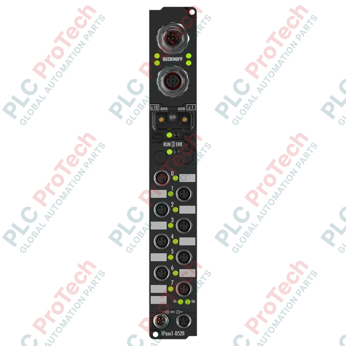
The DeviceNet Node ID (MAC ID) and network transmission speed are configured via rotary switches located underneath the transparent protective screw-cap on the front face. Ensure that the module's 24 V DC logic power supply is separate from the high-current output load supply to isolate the communications transceiver from inductive switching noise.
Installation Guidelines
CRITICAL WARNING
Disconnect all control and load power supplies prior to establishing or modifying physical network connections. Working on live DeviceNet trunks or active M8 I/O cabling can cause short-circuits, trigger sudden machine motion, or damage the communications transceivers.
1
Mount the Fieldbus Box on a flat, vibration-dampened surface using M4 screws through the integrated mounting ears.
2
Set the DeviceNet node address and baud rate via the rotary switches under the transparent cover, then securely torque the cover to maintain sealing.
3
Connect the DeviceNet trunk lines and route all M8 sensor and actuator cables. Hand-tighten all connectors, then tighten to the manufacturer's specified torque.