Description
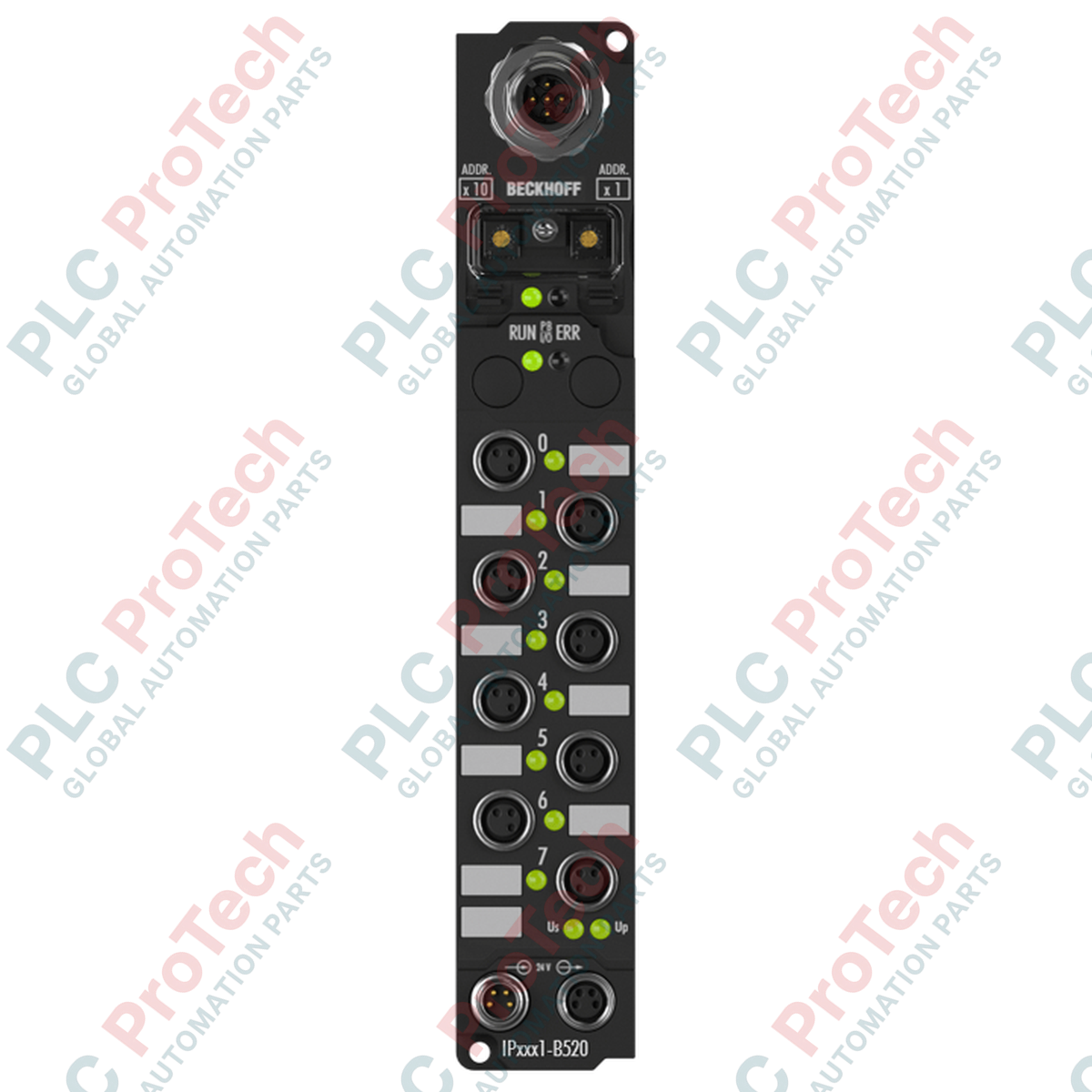
Designed to streamline decentralized control architectures, the Beckhoff IP2331-B520 acts as a rugged link between IP67-rated peripheral modules and a standard DeviceNet industrial network. By facilitating remote I/O processing directly at the machine level, this module eliminates the need for protective control cabinets and extensive parallel wiring. It dynamically handles both digital and analog peripheral signals, automatically matching the requirements of connected extension interfaces. Network configuration is easily managed using the KS2000 software tool or via explicit messaging through the host controller.
Features
-
DeviceNet Auto-Baud Rate: Features automatic transmission rate detection up to 500 kbaud for rapid fieldbus integration.
-
Flexible Signal Mapping: Automatically adapts processing of digital and analog peripheral signals based on the active I/O modules.
-
Independent Circuit Supplies: Utilizes isolated 24 V DC control and load power paths to protect internal logic from heavy actuator loads and safety shutdowns.
-
Ruggedized IP67 Form Factor: Dust-tight and moisture-proof construction enables direct machine mounting in harsh industrial processing areas.
-
Versatile Communication Modes: Supports key DeviceNet messaging structures including cyclic, change of state (COS), bit strobe, and polling modes.
Applications
-
Automotive Assembly Lines: Distributed sensor and actuator coordination directly on robot arms and heavy assembly machinery.
-
Packaging and Material Handling: Localized conveyor control and sensor arrays in high-speed sorting facilities.
-
Machine Tool Manufacturing: Cabinet-free deployment on metalworking and CNC centers exposed to cutting fluids and vibration.
Technical Specifications
| Parameter |
Specification |
| Manufacturer |
Beckhoff |
| Model Number |
IP2331-B520 |
| Fieldbus Interface |
DeviceNet |
| Bus Connection |
1 x M12 plug, 5-pin |
| Data Transfer Rate |
Automatic detection up to 500 kbaud |
| Control Voltage Supply |
24 V DC (-15% / +20%) |
| Load Voltage Supply |
Dependent on connected I/O type |
| Internal Box Current Consumption |
45 mA + sensor current (max. 0.5 A) |
| Power Connections |
Feed: 1 x M8 male (4-pin); Downstream: 1 x M8 female (4-pin) |
| Isolation Voltage |
500 V (Control voltage / fieldbus) |
| Operating Temperature |
0 to +55 degC |
| Storage Temperature |
-25 to +85 degC |
| Protection Rating |
IP65 / IP66 / IP67 (conforms to EN 60529) |
| Standards compliance |
Vibration EN 60068-2-6, Shock EN 60068-2-27, EMC EN 61000-6-2/4 |
| Approvals |
CE, UL |
| Shipping Weight (Calculated) |
2.0 kg |
Connections and Interfaces
| Connection Type |
Pin Mapping & Assignment |
| DeviceNet M12 Bus Plug (5-pin) |
Pin 1: Shield | Pin 2: V+ | Pin 3: V- | Pin 4: CAN_H | Pin 5: CAN_L |
| Power Feed M8 Male (4-pin) |
Pin 1: Feed 24 V DC Control | Pin 2: Feed 24 V DC Load | Pin 3: GND Control | Pin 4: GND Load |
| Power Downstream M8 Female (4-pin) |
Pin 1: Loop 24 V DC Control | Pin 2: Loop 24 V DC Load | Pin 3: GND Control | Pin 4: GND Load |
Empirical Engineering Insights
Alternative Models & Compatibility
The IP2331-B520 offers functional backward compatibility with the earlier legacy IP2330 model series. However, to maintain high-integrity diagnostic communication under DeviceNet, network masters must be updated with the correct Electronic Data Sheet (EDS) matching the B520 firmware revision. System upgrades must verify device configuration files before deployment.
Application Pitfalls & Engineering Notes
When daisy-chaining power across multiple modules via the M8 connectors, ensure the total loop-through current does not exceed the absolute limit of 4 A. Exceeding this threshold can lead to localized thermal degradation inside the terminal housing and cause unexpected communication drops. Separate isolated power lines should be run for control networks to avoid high-inductance electrical noise feedback on the data bus.
Commissioning & Wiring Tips
For successful automatic baud-rate determination, at least one node must actively transmit data on the DeviceNet network. Always terminate both far ends of the physical trunk with a 120-ohm resistor. If troubleshooting fieldbus signals, check the integrated status LEDs for common DeviceNet physical layer issues, such as grounding offsets between remote power drops.
Installation Guidelines
CRITICAL WARNING: De-energize all primary, auxiliary, and actuator power sources before performing any wiring or installation tasks on the fieldbus node. Failure to completely isolate control and load power supplies can result in hazardous short circuits, permanent transceiver damage, or physical machinery startup hazards.
1
Mount the Fieldbus Box onto a clean, flat surface using two M4 bolts, tightening them to a torque of 1.2 Nm to prevent structural strain on the plastic body.
2
Configure the physical DeviceNet node address using the hardware rotaries or DIP switches prior to powering up the system.
3
Firmly hand-tighten the M12 DeviceNet and M8 power cables to maintain their environmental IP67 seal integrity; do not use pliers, which can crack the threaded couplings.
4
Apply control voltage first to verify communications, then turn on the load voltage supply loop to enable peripheral sensors and field actuators.