Description
Designed to facilitate decentralized field installation, the Beckhoff IP5109-B400 offers robust distribution of digital and analog peripheral signals directly at the machine level. This module eliminates the requirement for protective enclosures by integrating an IP65/66/67 protection rating directly into its structural housing. It establishes network communication through a standard M23 bus interface and features a highly efficient loop-through power distribution architecture via integrated M8 power sockets. Configuration, diagnostics, and parameterization are managed seamlessly utilizing the specialized Beckhoff KS2000 software tool, ensuring direct integration with broader control topologies.
Features
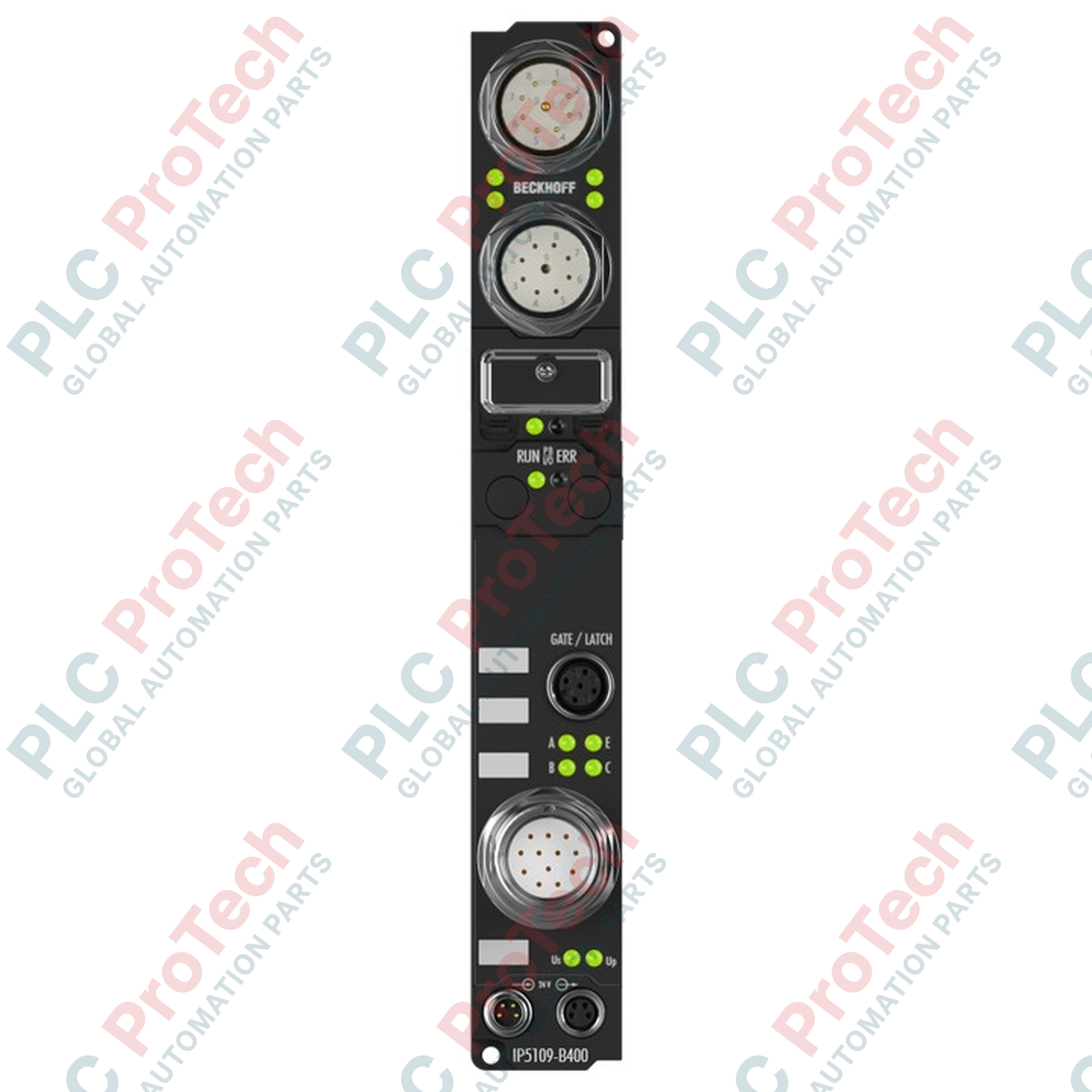
- Dual 9-pin M23 connectors (1 x female, 1 x male) for high-integrity bus lines.
- Direct machine mounting with comprehensive environmental sealing up to IP67.
- Integrated power distribution using 4-pin M8 modules for upstream feed and downstream looping.
- Configuration and setup integration via KS2000 software platform.
- Designed for harsh environments with certified resistance to vibration and mechanical shock.
Applications
- Decentralized input/output collection in large-scale material handling and conveyor installations.
- Automotive assembly lines requiring direct-mount machine control elements.
- Packaging machinery environments subject to regular washdowns and high-moisture exposure.
Technical Specifications
| Parameter |
Specification Value |
| Manufacturer |
Beckhoff |
| Model / Article Number |
IP5109-B400 |
| Bus Interface |
1 x M23 female socket (9-pin), 1 x M23 male socket (9-pin) |
| Control Voltage Supply |
24 V DC (20...29 V DC) |
| Load Voltage Supply |
According to I/O type specification |
| Power Supply Connections |
Feed: 1 x M8 male (4-pin); Downstream: 1 x M8 female (4-pin) |
| Internal Box Supply Current |
85 mA + sensor current consumption (max. 0.5 A) |
| Electrical Isolation |
Control voltage/fieldbus: No |
| Operating Temperature |
0 to +55 degC |
| Storage Temperature |
-25 to +85 degC |
| Protection Rating |
IP65/66/67 (conforms to EN 60529) |
| Vibration / Shock Resistance |
Conforms to EN 60068-2-6 / EN 60068-2-27 |
| EMC Immunity / Emission |
Conforms to EN 61000-6-2 / EN 61000-6-4 |
| Net Weight |
350 g |
| Shipping Weight (Calculated) |
2.0 kg |
Connections and Interfaces
| Connector Reference |
Connector Type |
Function Assignment |
| Bus Input |
9-pin M23 male socket |
Incoming fieldbus communication line |
| Bus Output |
9-pin M23 female socket |
Downstream loop-through fieldbus connection |
| Power Feed |
4-pin M8 male plug |
Primary 24 V DC control voltage input |
| Power Downstream |
4-pin M8 female socket |
Loop-through 24 V DC control voltage output |
Empirical Engineering Insights
Alternative Models & Compatibility
The IP5109-B400 utilizes standard Fieldbus Box architectural footprints. When replacing legacy Beckhoff IP-series modules, ensure that the GSD, EDS, or TwinCAT XML device description files in the master PLC are updated to match the specific revision and hardware configuration of this B400-variant unit to prevent network mapping mismatch faults.
Application Pitfalls & Engineering Notes
Be aware of the total power distribution path. When looping multiple modules via the M8 downstream interfaces, the aggregate sensor current draw must not exceed 0.5 A per box. Exceeding this limit leads to voltage drop-offs and potential control-side power brownouts, particularly along long daisy-chain configurations in high-vibration zones.
Commissioning & Wiring Tips
To guarantee IP67 protection integrity over life cycles, M8 and M23 connections should be tightened using a calibrated torque wrench to the exact manufacturer-specified torque values. Over-tightening can crush the internal rubber O-rings, leading to moisture ingress during high-pressure machine washdowns, while under-tightening compromises electrical contact under mechanical stress.
Installation Guidelines
CRITICAL WARNING
Ensure all power supplies feeding the M8 connection lines and control buses are physically locked out and de-energized before mounting, wiring, or configuring the device. Failure to completely isolate the power can result in system short circuits, driver damage, or localized electrical faults.
1
Verify the physical integrity of the mounting location. Ensure the surface is flat to avoid structural stress on the fiber-reinforced plastic housing of the box.
2
Secure the unit using standard mounting bolts. Route the M23 bus input and output cables without tight bends to prevent shielding breakdown and EMI issues.
3
Connect the M8 power feed and loop-through cables. Fit protective dust caps on any unused M8 or M23 ports to maintain the IP67 environmental seal.