Description
Engineered for high-accuracy differential measurement in demanding automation architectures, the Beckhoff KS3132 is a premium 2-channel analog input terminal designed to interface directly with standard K-bus backplane systems. By processing voltage signals in the -10 V to +10 V range with a native 16-bit conversion engine, this unit translates physical inputs into precise digitized values with high immunity to common-mode electrical interference. The inclusion of a pluggable wiring system allows field technicians to remove and insert the active electronics cartridge without disturbing the pre-installed field wiring loom, minimizing system downtime during maintenance cycles.
Features
-
Dual-Channel Differential Inputs: Provides two independent differential analog channels to suppress common-mode noise across extended signal runs.
-
16-Bit Resolution: High-resolution sampling (15-bit resolution for standard 0 to 10 V scaling) ensures precise feedback for fine closed-loop processes.
-
Pluggable Wiring Level: The KS series architecture permits tool-free modular swapping while keeping the field wiring termination intact.
-
Configurable 50 Hz Filter: Built-in configurable low-pass filter specifically targeted to suppress industrial line frequency interference.
-
Galvanic Isolation: 500 V electrical isolation between the internal K-bus and the analog measurement circuitry to shield upstream controllers from field-side voltage transients.
Applications
-
Precision Positioning Systems: Interfacing with analog position feedback sensors, linear transducers, and encoders.
-
Process Instrumentation: Monitoring differential pressure transmitters, flow meters, and flow control loops.
-
Hazardous Area Control: Direct DIN-rail integration inside explosive environments matching ATEX Zone 2 design constraints.
Technical Specifications
| Parameter |
Value |
| Manufacturer |
Beckhoff |
| Model Number |
KS3132 |
| Number of Inputs |
2 |
| Signal Range |
-10 V to +10 V |
| Technology |
Differential Input |
| Internal Resistance |
> 70 kOhm |
| Common-Mode Voltage (Ucm) |
10 V maximum |
| Resolution |
16 bit (15 bit for 0 to 10 V range) |
| Conversion Time |
140 ms (configurable) |
| Hardware Filter |
50 Hz (configurable) |
| Measuring Error |
< ±0.05% (relative to full scale value) |
| Electrical Isolation |
500 V (K-bus / signal voltage) |
| K-Bus Current Consumption |
Typical 85 mA |
| Power Contact Contacts |
None |
| ATEX Classification |
II 3 G Ex nA IIC T4 Gc |
| Operating Temperature Range |
0 to +55 degC |
| Storage Temperature Range |
-25 to +85 degC |
| Relative Humidity |
95%, non-condensing |
| Housing Material |
Polycarbonate |
| Mounting |
35 mm DIN rail (EN 60715) with double slot lock |
| Dimensions (L x W x H) |
68 mm x 12 mm x 100 mm |
| Net Weight |
0.07 kg |
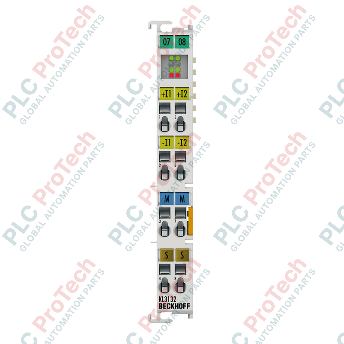
Connections and Interfaces
| Terminal Connection |
Signal Description |
| Terminal 1 |
Input + (Channel 1) |
| Terminal 5 |
Input - (Channel 1) |
| Terminal 2 |
Input + (Channel 2) |
| Terminal 6 |
Input - (Channel 2) |
| Terminal 3 |
Shield Connection (Channel 1) |
| Terminal 7 |
Shield Connection (Channel 2) |
| Terminal 4 / 8 |
No Connection (Internal reserve) |
Empirical Engineering Insights
Alternative Models & Compatibility
The KS3132 shares identical software registers, electrical parameters, and TwinCAT process image structures with the standard KL3132. The primary differentiator is the KS series pluggable connector housing. If standard-wired KL3132 modules are present in your existing fieldbus nodes, they can be directly interchanged with the KS3132 provided the terminal connector head matches the plug-in base pattern.
Application Pitfalls & Engineering Notes
Because this module does not route power contacts to the adjacent bus slices (it does not feature power rail pass-through tabs), it cannot feed operating current to field-side instruments. Loop or external auxiliary power must be provided downstream. Additionally, when using the 0 to 10 V input profile, the physical resolution drops from the bipolar 16 bits to 15 bits. System designers must account for this reduction in quantization when writing process automation calculations.
Commissioning & Wiring Tips
Always employ shielded twisted pair (STP) wiring for both differential paths. Connect the shielding drain wire directly to terminals 3 or 7 on the module, or to a low-impedance grounding bar positioned near the entry point of the control panel. If you experience signal attenuation or measurement oscillation, confirm that the TwinCAT register configurations match your filter profiles; the internal 50 Hz digital notch filter can be modified in software using direct register access paths (specifically Register R32).
Installation Guidelines
CRITICAL WARNING
Isolate all electrical feeds to the K-bus coupler and external field sensors before inserting, extracting, or wiring the module. Working on live active terminal blocks poses a risk of damaging internal backplane optocouplers and can cause process disruptions on neighboring nodes.
1
Mount the terminal block body by sliding it onto standard 35 mm DIN rail until the lock mechanism clicks firmly, aligning the slide keys with adjacent terminals.
2
Using a flat-head screwdriver (0.4 x 2.5 mm), actuate the cage clamp spring mechanisms to terminate the field inputs using the proper stripping length of 9 to 10 mm.
3
Plug the pre-wired connector block into the KS3132 base unit, ensuring that the locking lugs click securely into position.
4
Power on the bus coupler and execute the TwinCAT configuration scan to confirm that the node reports error-free process data transmission status.