Description
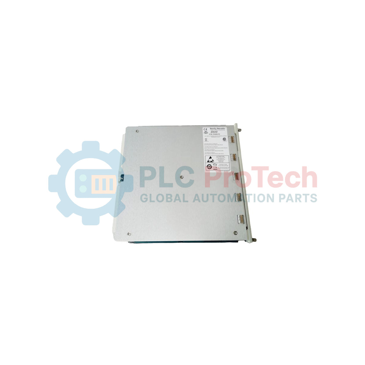
Facilitating high-speed, noise-immune communication within the 3500 machinery protection rack, the Bently Nevada 147364-01 acts as a physical interface for external Ethernet connections. This specific 100Base-FX fiber optic I/O module mounts in the rear of the rack, directly aligning with the 3500/92 Communication Gateway to transmit vital machinery diagnostics and monitoring parameters over optical networks. By substituting traditional copper connections with fiber optics, it provides absolute electrical isolation and eliminates ground loop issues in demanding industrial telemetry layouts.
Features
-
100Base-FX Standard: Operates at 100 Mbps over multi-mode optical fiber.
-
Complete Optical Isolation: Prevents electromagnetic interference (EMI) and radio frequency interference (RFI) from degrading signal integrity.
-
Dual SC Connectors: Direct interface for TX and RX fiber lines, securing rugged and reliable connections.
-
Direct Gateway Interface: Installs back-to-back with the 3500/92 gateway to facilitate seamless Modbus/TCP or proprietary Ethernet communication.
-
Heavy Industrial Build: Rated for survival in harsh backplane operating environments.
Applications
- High-voltage electrical switchyards where copper-based networks face induction hazards.
- Long-distance machinery monitoring installations stretching up to two kilometers without signal repeaters.
- Petrochemical, oil and gas, and power generation facilities requiring spark-free transmission media.
Technical Specifications
| Parameter |
Specification |
| Manufacturer |
Bently Nevada |
| Part Number |
147364-01 |
| Physical Layer Protocol |
100Base-FX (IEEE 802.3u) |
| Transmission Medium |
Multi-Mode Fiber Optic (62.5/125 um or 50/125 um) |
| Interface Connectors |
Dual SC Connectors (TX / RX) |
| Optical Wavelength |
1300 nm |
| Compatible Gateway Module |
3500/92 Communication Gateway |
| Operating Temperature Range |
-30 degC to +65 degC |
| Country of Origin |
USA |
| Shipping Weight (Calculated) |
3.0 kg |
| Package Dimensions (Calculated) |
245 mm x 115 mm x 25 mm |
Connections and Interfaces
| Port Label |
Connection Function / Specification |
| TX |
Optical Transmitter Port; outputs 1300 nm multi-mode light signal to network switch receiver. |
| RX |
Optical Receiver Port; inputs incoming 1300 nm light signal from network switch transmitter. |
Alternative Models & Compatibility
The 147364-01 multi-mode fiber optic I/O module serves as a direct alternative to copper-based I/O variants of the 3500/92 system, such as those utilizing RJ45 connections (e.g., 100Base-TX). When transitioning from a copper I/O card to the 147364-01, verify that your front-facing 3500/92 gateway module possesses firmware capable of recognizing 100Base-FX interfaces, preventing configuration faults in the Bently Nevada 3500 Rack Configuration Software.
Application Pitfalls & Engineering Notes
A common site engineering oversight involves attempting to couple this multi-mode card with single-mode (SM) fiber runs. Standard single-mode fibers have a much narrower core and will result in high optical attenuation, causing communication failures or intermittent Link/Act drops. To run this module over a single-mode infrastructure, you must integrate an external, industrially hardened multi-mode to single-mode fiber media converter.
Commissioning & Wiring Tips
Always check the RX and TX crossover mapping. The TX port on the 147364-01 module must patch directly to the RX port of the network equipment, and vice versa. Keep the fiber optic dust caps secured onto the SC ports until the physical patch cords are ready for insertion. Airborne particulate matter common in industrial environments can contaminate the internal optical barrel, requiring specialized dry-swab cleaning to restore nominal db levels.
Installation Guidelines
CRITICAL WARNING:
Do not insert or remove the rear I/O module while power is applied to the 3500 rack system. Uncontrolled power surges can cause backplane errors and physical damage to sensitive optical transceiver circuitry. Ground yourself to the rack chassis using an ESD strap before handling the hardware.
1
De-energize the entire 3500 rack power supplies and verify using a calibrated voltmeter.
2
Align the module with the card guides in the backplane slot directly behind the corresponding 3500/92 Communication Gateway.
3
Slide the module forward carefully until the backplane connectors seat completely.
4
Securely tighten the captive screws on the front panel of the 147364-01 module to establish chassis grounding.
5
Uncap the SC fiber optic connectors and patch the multi-mode cabling to the ports.