Description
Engineered for critical machinery protection systems, the Bently Nevada 330102-00-20-10-00-00 is a high-precision 3300 XL series 8 mm proximity probe designed to monitor radial vibration, axial position, and keyphasor reference measurements on high-speed rotating shafts. This robust transducer features a 3/8-24 UNF threaded body fitted with integral fluid-resistant flexible armor to shield the internal coaxial line from harsh industrial environments. By providing continuous, non-contact displacement measurements, it prevents catastrophic mechanical failures in steam turbines, gas turbines, compressors, and high-performance pumps.
Features
-
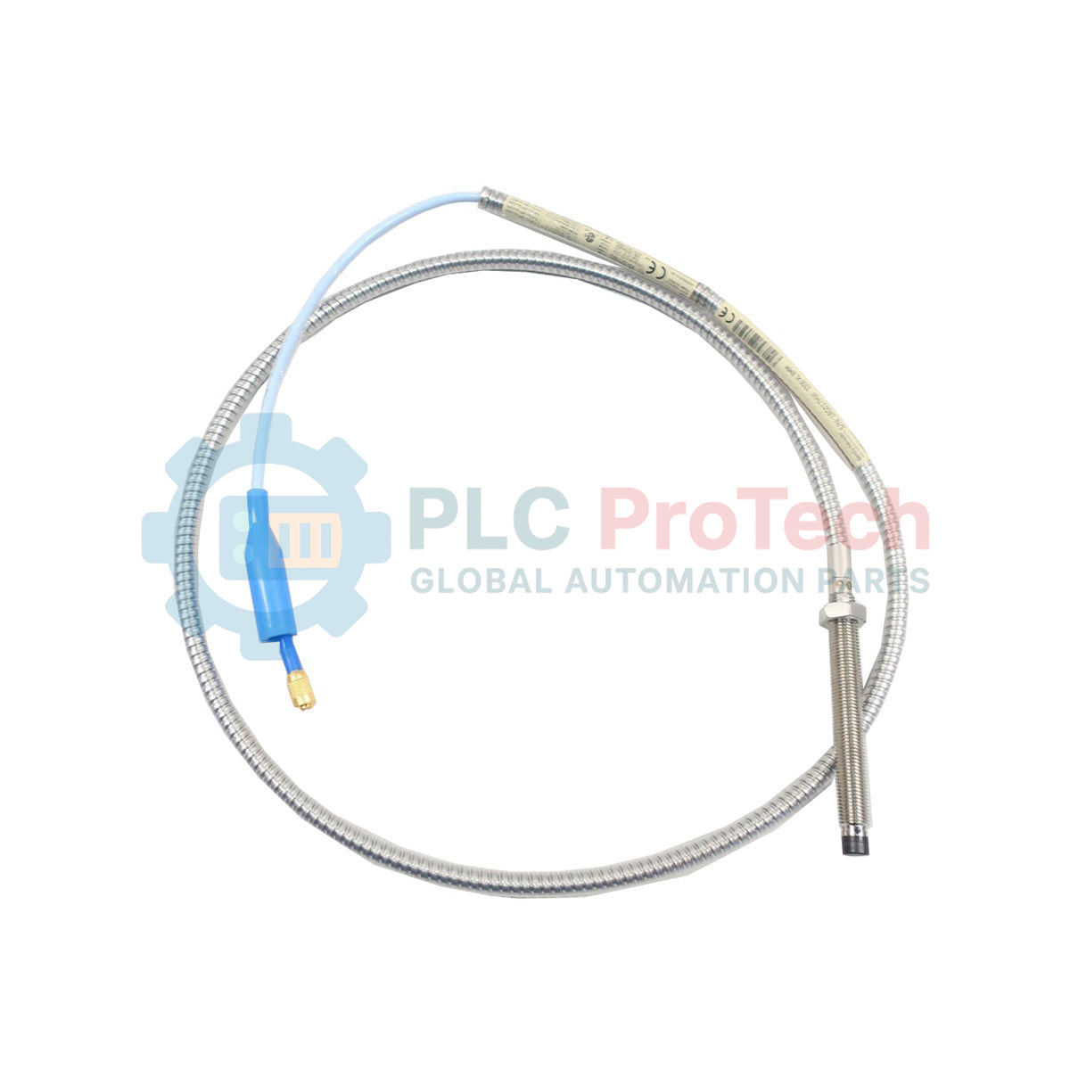
Thread and Armor Configuration: Standard 3/8-24 UNF threads with rugged, fluid-resistant stainless steel armor, preventing cable cuts and abrasion in high-wear zones.
-
ClickLoc Connector System: Equipped with corrosion-resistant Gold-plated miniature coaxial connectors that lock securely to prevent signal loss caused by vibration.
-
Fully Standard Compliant: Fully meets the mechanical and electrical specifications of API 670 standards for machinery protection systems.
-
System Interchangeability: Completely interchangeable with other Bently Nevada 3300 XL 8 mm probes, extension cables, and Proximitor sensors without requiring individual recalibration.
-
Extreme Environment Tolerant: High chemical and thermal resistance, designed to withstand continuous exposure to synthetic lubricating oils, moisture, and aggressive industrial solvents.
Applications
- Turbine shaft radial dynamic vibration monitoring.
- Centrifugal compressor axial thrust position tracking.
- High-speed industrial gearbox bearing wear analysis.
- Hydroelectric generator shaft runout and alignment verification.
- Phase reference (Keyphasor) speed measurements.
Technical Specifications Table
| Parameter |
Specification Value |
| Manufacturer |
Bently Nevada |
| Model Code |
330102-00-20-10-00-00 |
| Product Series |
3300 XL 8 mm Proximity Transducer System |
| Thread Size |
3/8-24 UNF |
| Unthreaded Length Option (00) |
0.0 inches (0 mm) |
| Overall Case Length Option (20) |
2.0 inches (51 mm) |
| Total Length Option (10) |
1.0 meter (3.3 feet) |
| Cable Armor Option |
Fluid-resistant stainless steel armor |
| Connector Option (00) |
Miniature coaxial ClickLoc connector, standard plug |
| Agency Approval Option (00) |
No approvals required (General Purpose) |
| Linear Range |
2.0 mm (80 mils), nominal |
| System Compatibility |
3300 XL Proximitor Sensor & Extension Cable |
| Operating Temperature Range |
-51 degC to +177 degC (-60 degF to +350 degF) |
| Country of Origin |
United States (USA) |
| Net Physical Weight |
0.323 kg (0.71 lbs) |
| Shipping Weight (Calculated) |
1.500 kg (3.30 lbs) |
| Package Dimensions (Calculated) |
250 x 200 x 50 mm (9.8 x 7.9 x 2.0 in) |
Connections and Interfaces
| Connector Part |
Electrical Mapping |
Function / Shielding |
| Center Conductor Pin |
Signal High (AC/DC RF) |
Transmits high-frequency excitation signal from Proximitor to the probe coil. |
| Outer Coaxial Sleeve |
Signal Common (COM) |
Ground reference and signal return path. |
| Flexible Protective Armor |
Chassis Ground (Isolated) |
Acts as a Faraday shield against low-frequency electromagnetic interference. |
Empirical Engineering Insights
Alternative Models & Compatibility
While the 3300 XL 8 mm system is backward compatible with non-XL 3300 5 mm and 8 mm system components, mixing components results in degraded performance. For instance, pairing an XL probe with a non-XL Proximitor sensor reduces the linear range and decreases thermal stability from +177 degC down to standard limits. Always match probe and extension cable total electrical lengths (e.g., this 1.0 m probe requires a 4.0 m extension cable to complete a standard 5.0 m loop configuration).
Application Pitfalls & Engineering Notes
The target shaft must have a minimum diameter at least three times the diameter of the probe tip (minimum target diameter of 24 mm / 0.95 inches). Shaft diameters below this limit cause severe magnetic field distortion (side-viewing effects), resulting in non-linear voltage outputs. Additionally, ensure the shaft material is AISI 4140 steel; other materials like stainless steel or monel alter eddy current penetration, requiring physical sensor recalibration or custom scale factors.
Commissioning & Wiring Tips
During mechanical installation, always verify the probe gap using a static spindle micrometer and a digital voltmeter connected to the Proximitor sensor output. Set the nominal physical gap to generate approximately -10.0 VDC (the center point of the 3300 XL's linear range). Ensure the coaxial connectors are tightened securely using standard Bently Nevada connector tools; over-tightening or twisting the armor body can permanently damage the internal coaxial solder junctions.
Installation Guidelines
CRITICAL FIELD WARNING:
Before attempting installation, ensure the monitored machinery is completely de-energized and locked out. Do not perform probe gap adjustments while the shaft is rotating. To prevent electrostatic discharge (ESD) from damaging the probe tip or the Proximitor internal circuitry, discharge all body static by touching a grounded structure before handling the connector plug.
1
Prepare Mount Location: Inspect the threaded mounting port on the machine housing. Ensure threads are clean and free of metal burrs or residual thread sealant.
2
Verify Clearance and Route Cable: Thread the probe body into the mounting hole by rotating the entire probe assembly (to prevent twisting the armored cable) until the tip approaches the target shaft.
3
Set Probe Gap: Using a calibrated digital multimeter connected to the Proximitor "OUT" and "COM" terminals, adjust the probe depth until the output voltage reads exactly -10.0 VDC. Tighten the locknut to 11.3 N-m (100 in-lb) of torque.