Description
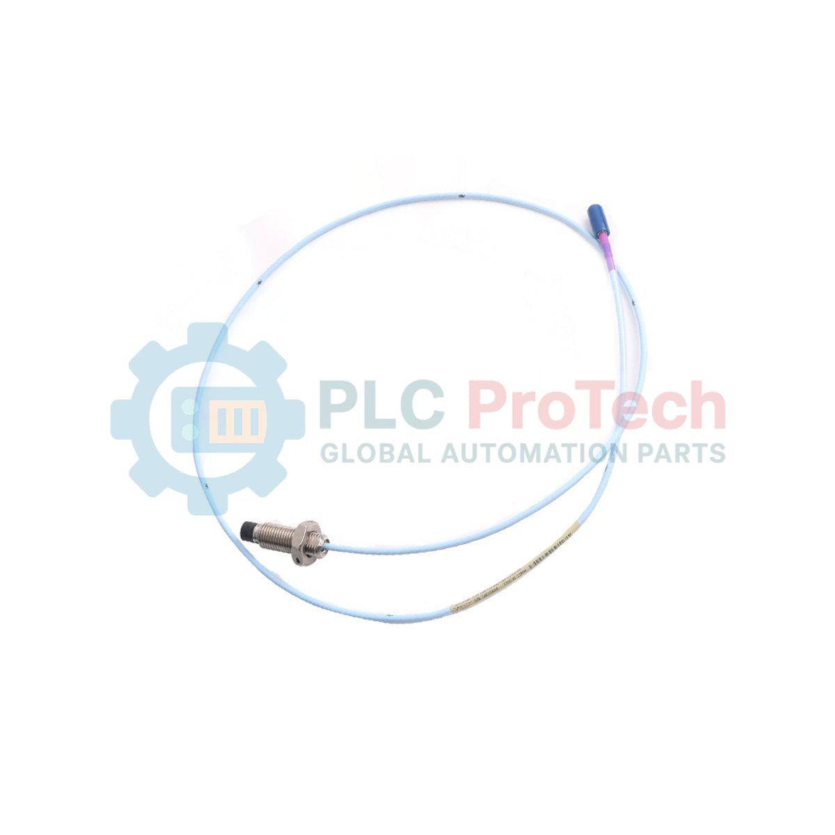
Designed for continuous shaft vibration and axial position measurements in extreme thermal environments, the Bently Nevada 330302-000-050-10-90-01-00 serves as a highly robust transducer within the 3300 series machinery protection ecosystem. This proximity probe features a specialized hardline cable construction that isolates the sensitive coaxial connection from high-temperature zones. With its 0 mm unthreaded length, 50 mm overall case length, and 1.0-meter hardline section, the probe ensures physical stability and precise sensor-to-target gapping in tight turbine casings. The fully integrated system features a total length of 9.0 meters protected by durable stainless steel armor, providing seamless integration with compatible proximity transducer systems without requiring agency approvals.
Features
-
Extreme Thermal Performance: Engineered with a hardline cable section to withstand the demanding thermal profiles of gas and steam turbine casings.
-
Durable Mechanical Armor: Equipped with Option 01 stainless steel outer armor to protect the extension cable from mechanical shearing, abrasion, and routing stress.
-
Optimized Probe Case: Features a compact 50 mm case length with zero unthreaded length, allowing flush-mount or low-profile bracket configurations.
-
Extended Reach: Total system length of 9.0 meters simplifies routing from the high-temperature machine core to external connection junction boxes.
-
Interchangeable Design: Standard mechanical and electrical specifications ensure precise compatibility with Bently Nevada monitoring systems.
Applications
- Continuous monitoring of steam turbine casing expansion and rotor vibration.
- Axial position and radial vibration measurements near gas turbine exhaust frames.
- Industrial machinery monitoring in process environments with ambient temperatures exceeding standard limits.
- High-temperature fans, blowers, and turbocompressor bearing housings.
Technical Specifications
| Parameter |
Specification |
| Manufacturer |
Bently Nevada |
| Model Number |
330302-000-050-10-90-01-00 |
| Product Line |
3300 High Temperature Proximity Probe |
| Unthreaded Length |
0 mm (000 Option) |
| Overall Case Length |
50 mm (050 Option) |
| Hardline Length |
1.0 meter / 3.3 feet (10 Option) |
| Total System Length |
9.0 meters / 30 feet (90 Option) |
| Cable Protection |
Stainless Steel Armor (01 Option) |
| Agency Approval |
Not Required (00 Option) |
| Country of Origin |
U.S.A. |
| Shipping Weight (Calculated) |
2.0 kg |
Empirical Engineering Insights
Alternative Models & Compatibility
This high-temperature probe requires matching with specific high-temperature Proximitor sensors calibrated for the 3300 HT system. Standard 3300 XL 8mm Proximitor sensors may lack the exact compensation profile required for this high-temperature probe tip material, resulting in scale factor errors. Ensure the entire loop (probe, extension cable, and Proximitor) shares consistent system length parameters (9.0 meters).
Application Pitfalls & Engineering Notes
The 1.0-meter hardline cable transition section is semi-rigid. Mechanical fatigue can occur if this section is subjected to continuous, high-amplitude structural vibration without proper intermediate clamping. Additionally, because thermal expansion affects probe-tip-to-target distance, static mechanical gapping calculations must factor in the expansion coefficients of both the turbine housing and the probe assembly itself at full operating temperature.
Commissioning & Wiring Tips
Never bend the hardline portion of the probe to a radius of less than 50 mm. Sharp kinks will permanently change the characteristic impedance of the coaxial core, causing signal reflection and calibration invalidation. When joining the probe connector to the armored extension cable, apply self-fusing silicone tape over the junction to seal against moisture and high-humidity oil mist common in turbine enclosures.
Installation Guidelines
CRITICAL WARNING
Isolate, lock out, and de-energize the monitored machinery before starting the installation process. Ensure the casing surfaces and surrounding air have cooled to a safe handling threshold. High-temperature surfaces pose a severe thermal hazard, and mechanical rotation during installation can cause severe hardware damage or personal injury.
1
Carefully feed the probe tip through the mounting bracket, keeping the 1.0-meter hardline section straight to avoid structural strain or structural bending.
2
Thread the 50 mm probe case into the mount, adjusting the depth while checking clearance to prevent the probe face from contacting the target shaft.
3
Utilize a digital voltmeter connected to the corresponding Proximitor sensor's OUT terminal to monitor DC bias voltage, aiming for the specified mid-range voltage calibration point.
4
Secure the locking nut to lock the probe in place, then route the armored extension cable through protective industrial conduit to prevent physical wear.