Description
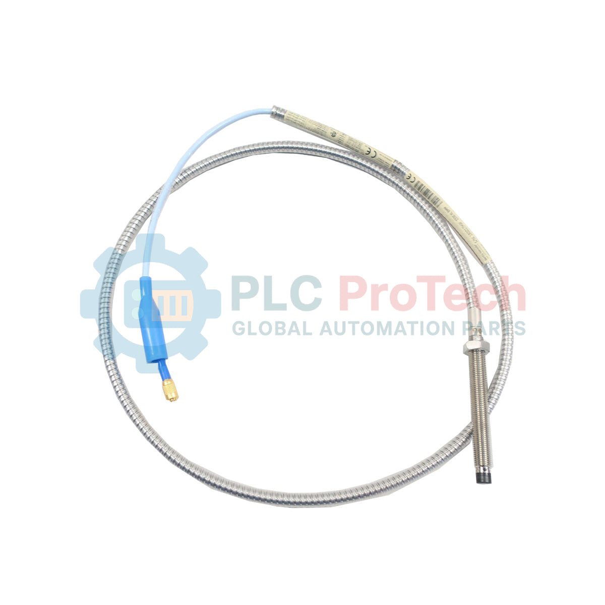
Engineered for critical machinery protection and condition monitoring systems, the Bently Nevada 330103-00-02-10-02-CN operates as a non-contacting transducer designed to measure static and dynamic shaft displacement. This 3300 XL 8 mm series probe delivers high-accuracy eddy current measurements, providing vital physical gap telemetry to Proximitor sensors in high-velocity steam turbines, compressors, and industrial pumps. Incorporating a specialized ClickLoc connector and robust physical armor options, this configuration ensures reliable signal transmission in demanding, high-temperature industrial environments.
Features
-
High-System Interchangeability: Fully compatible with standard Bently Nevada 3300 XL 8 mm series Proximitor sensors and extension cables without requiring individual recalibration.
-
ClickLoc Coaxial Connection: Equipped with a miniature coaxial ClickLoc connector to resist physical disconnection and environmental ingress at critical junction points.
-
Chemical and Moisture Resistance: Designed to withstand exposure to corrosive lubricating oils, process fluids, and harsh industrial cleaning agents.
-
Precision Tip Construction: Features an 8 mm probe tip engineered for thermal stability and high-linearity measurement output.
Applications
-
Turbine Generator Sets: Real-time monitoring of radial vibration and axial thrust position in heavy-duty utility steam and gas turbines.
-
Process Compressors: Shaft centerline and oil-film bearing displacement tracking in centrifugal and reciprocating gas compressors.
-
Industrial Gearboxes: Early detection of shaft misalignment and gear mesh wear through sub-micron shaft motion analysis.
-
High-Speed Pumps: Continuous rotor dynamics feedback for critical boiler feed pumps and fluid processing machinery.
Ordering Information
| Option Code |
Configuration Detail |
Value / Dimension |
| 00 |
Unthreaded Length |
0 mm |
| 02 |
Overall Case Length |
20 mm |
| 10 |
Total Length |
1.0 meter (3.3 feet) |
| 02 |
Connector and Cable Type |
Miniature coaxial ClickLoc connector, standard cable |
| CN |
Agency Approval |
Country-specific approvals (China/CN) |
Technical Specifications
| Manufacturer |
Bently Nevada (Baker Hughes) |
| Model Code |
330103-00-02-10-02-CN |
| Probe Tip Diameter |
8 mm |
| System Linear Range |
2.0 mm (80 mils) nominal (starting at 0.25 mm/10 mils offset) |
| Nominal Scale Factor |
7.87 V/mm (200 mV/mil) when integrated into full 3300 XL system |
| Operating Temperature Range |
-51 degC to +177 degC (-60 degF to +350 degF) |
| Connector Material |
Gold-plated brass with ClickLoc quick-lock connection |
| Country of Origin |
United States (U.S.A.) |
| Shipping Weight (Calculated) |
1.5 kg (3.3 lbs) package weight |
Empirical Engineering Insights
Alternative Models & Compatibility
While the 3300 XL 8 mm proximity probe system retains backward mechanical compatibility with standard 3300 series 5 mm and 8 mm components, combining XL and non-XL systems will alter the calibrated scale factor. For optimal calibration stability and linear output, ensure that this 1.0-meter probe is paired with a corresponding 3300 XL 8 mm Proximitor sensor and a total-system-length matching extension cable (yielding either 5.0m or 9.0m total system loop configurations).
Application Pitfalls & Engineering Notes
When deploying the unthreaded (00) option, ensure the mounting clamp or sleeve provides sufficient structural rigidity to prevent probe displacement under high-vibration conditions. Observe strict side-clearance tolerances: a minimum of 15 mm of flat target area diameter is required directly in front of the 8 mm tip to prevent target-fringe inaccuracies. Avoid routing the coaxial signal cable alongside high-power AC motor or variable speed drive (VSD) supply lines to minimize magnetic cross-talk and EMI induction.
Commissioning & Wiring Tips
Before mating the miniature ClickLoc coaxial connector, verify both contacts are free of moisture, lubricating oil, and particulate debris. Use dedicated coaxial connector silicone boots or sealing kits at joint interfaces in environments containing high humidity or aerosolized process fluids. Always verify the overall system loop resistance and insulation resistance to ground before connecting the circuit back to the local Proximitor terminal block.
Installation Guidelines
CRITICAL WARNING: SAFETY INSTRUCTIONS
De-energize all machinery and power circuits before installing or adjusting proximity probes. Failure to physically isolate equipment from rotational power sources can cause severe injury or equipment destruction. Ensure localized environments match hazardous area certification classifications specified by the "CN" suffix documentation before physical installation.
1
Inspect the shaft surface target area. Ensure it is free of physical scratches, burrs, or electromagnetic runout markings that could distort displacement signals.
2
Mount the probe using a precision sleeve or bracket, ensuring the unthreaded 20 mm case length aligns correctly within the installation bore.
3
Apply a digital voltmeter (DVM) to the Proximitor monitor output terminals to monitor gap voltage during manual insertion. Position the probe to yield a -10.0 Vdc bias reading (center of linear range) before securing physical locknuts.
4
Route and anchor the 1.0-meter probe cable through dedicated protective conduit, observing minimum bend-radius specifications of 25.4 mm (1.0 inch).