Description
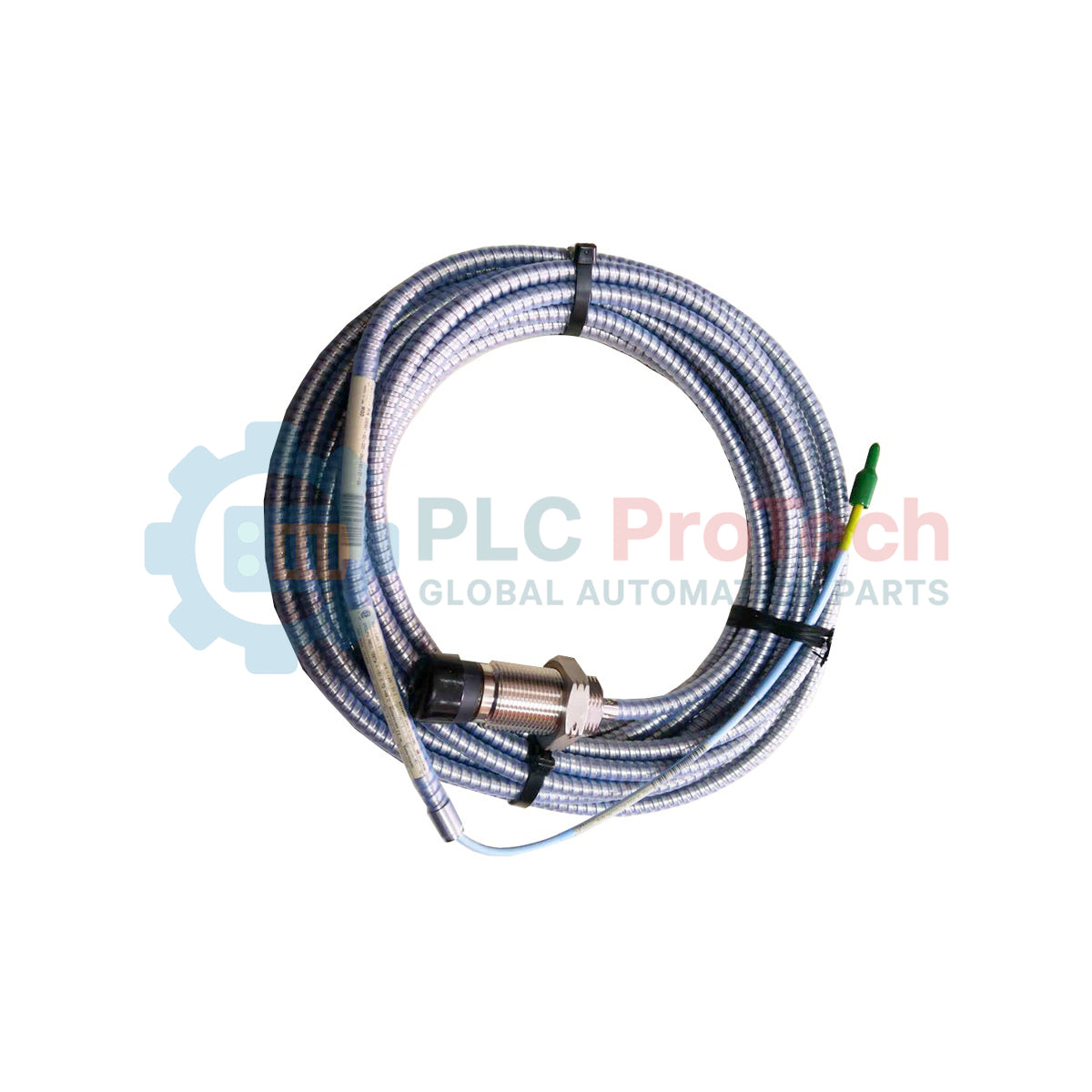
Providing reliable displacement and vibration measurements on large utility turbomachinery, the Bently Nevada 330851-02-000-050-10-01-CN is engineered for high-precision monitoring in demanding industrial environments. As a primary sensor within the 3300 XL 25 mm Proximity Transducer System, this probe is configured with an M30x2 metric thread body, zero unthreaded length, a 50 mm overall case length, and a 1.0-meter integrated cable protected by stainless steel armor. Built with high-grade Polyetheretherketone (PEEK) tip materials and a corrosion-resistant AISI 304 stainless steel housing, the assembly withstands severe thermal cycling and chemical exposure. This specific model features country-specific agency approvals for reliable compliance in globally managed production facilities.
Features
-
Extended Linear Range: Specifically calibrated to provide long-range displacement monitoring on large machinery shafts.
-
FluidLoc Cable Technology: 75-ohm triaxial FluidLoc cable insulated with PFA prevents moisture or oil wicking through the core.
-
Robust Mechanical Armor: Stainless steel (AISI 302) armor with a PFA outer jacket protects against physical impacts and aggressive process fluids.
-
Premium Material Construction: PEEK tip and AISI 304 stainless steel case ensure maximum endurance against steam and chemicals.
-
Certified Performance: Configured with CN approval options for specific country electrical and safety compliance.
Applications
- Thrust and radial vibration monitoring in large steam and gas turbines.
- Differential expansion tracking in high-capacity utility generators.
- Shaft positioning measurements on process compressors and large industrial fans.
- Industrial machinery safety interlocks and protection systems.
Technical Specifications
| Parameter |
Specification Value |
| Manufacturer |
Bently Nevada |
| Part Number / SKU |
330851-02-000-050-10-01-CN |
| Product Series |
3300 XL 25 mm Proximity Transducer System |
| Probe Case Type |
M30x2 metric thread (Option 02) |
| Unthreaded Length |
0 mm (Option 000) |
| Overall Case Length |
50 mm (Option 050) |
| Total Cable Length |
1.0 meter (3.3 feet) (Option 10) |
| Cable Armor Option |
Flexible AISI 302 SST with PFA outer jacket (Option 01) |
| Probe Tip Material |
Polyetheretherketone (PEEK) |
| Probe Case Material |
AISI 304 stainless steel (SST) |
| Cable Impedance & Type |
75-ohm triaxial PFA-insulated FluidLoc cable |
| Operating / Storage Temp |
-35 degC to 200 degC (-31 degF to 392 degF) |
| Agency Approvals |
Country-specific hazardous area certifications (Option CN) |
| Net Weight |
0.330 kg (0.73 lbs) |
| Shipping Weight |
1.300 kg (2.87 lbs) |
Empirical Engineering Insights
System Length Calibration Matching
The 1.0-meter physical length of this probe must be paired with an appropriate 3300 XL extension cable to achieve a total calibrated electrical system length of either 5.0 or 9.0 meters. Substituting mismatched physical and electrical lengths or mixing 25 mm probes with non-matching Proximitor sensors causes substantial impedance discrepancies, yielding severe gap-voltage calibration errors.
Cabling and Armor Management
The SST armor provides high physical resistance but must not be bent past its minimum static bend radius of 25.4 mm (1.0 inch). Kinking or exceeding this limit damages the delicate 75-ohm triaxial FluidLoc core, leading to signal instability or loss of machinery protection functionality.
Installation Guidelines
CRITICAL WARNING: Ensure that the machinery to which this transducer is being attached is fully de-energized, isolated, and safe to work on before beginning physical installation. Ensure lockout/tagout procedures are strictly adhered to. Discharge any residual electrostatic energy from cables and components prior to finalizing physical sensor links in hazardous areas.
1
Mount the probe through a pre-drilled M30x2 metric tapped hole, utilizing a calibrated torque wrench to ensure secure locking without stressing the threaded housing or the internal PEEK tip assembly.
2
Route the armored cable to the junction box using cable trays or conduit. Avoid high-stress locations near moving components or extreme localized heat sources to ensure long-term stability.
3
Verify correct probe gap using a digital voltmeter. Calibrate the gap voltage according to system standards (typically -10 VDC at mid-scale for standard target materials) before commissioning.