Description
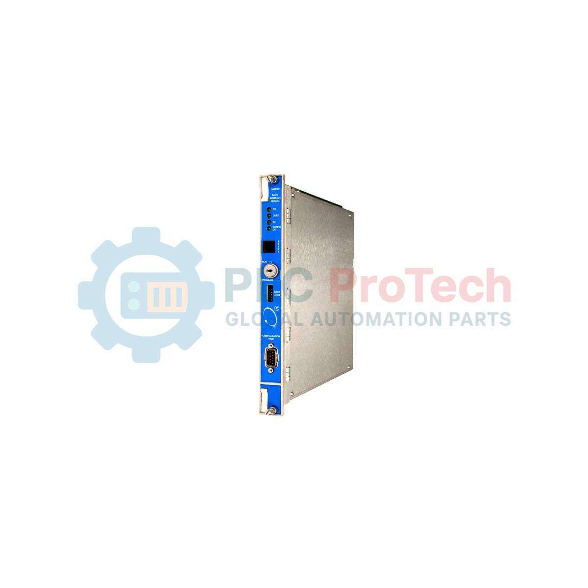
Integrating directly into the left-most slot of a 3500 machinery protection rack, the Bently Nevada 3500/20-01-02-00 functions as the primary communication gateway between the internal rack monitor modules and external control systems. This specific assembly is configured with standard Rack Interface Module (RIM) firmware and includes the RS232/RS422 serial interface I/O module. It serves as the physical and logical link for system configuration, status monitoring, and serial data integration. By routing critical machine status data through its serial interface, this module enables direct PLC or DCS communication without overloading the system configuration bus.
Features
- Establishes reliable serial communication links for DCS, PLC, and plant historian integration.
- Features standard RIM capabilities ideal for dedicated machinery protection and continuous monitoring.
- Includes the rear-mounted RS232/RS422 I/O module for flexible serial topology layouts.
- Supports remote or local configuration when paired with the Bently Nevada 3500 Rack Configuration Software.
- Maintains dedicated internal diagnostics to continually verify correct hardware operation.
Applications
- Integration of rotating machinery protection loops with plant-wide DCS platforms.
- Continuous monitoring of industrial turbines, compressors, and high-power pumps.
- Legacy serial Modbus configurations in oil, gas, and power generation facilities.
Technical Specifications
| Parameter |
Specification Value |
| Manufacturer |
Bently Nevada |
| Model Code |
3500/20-01-02-00 |
| Rack Interface Type |
Standard RIM (01) |
| I/O Module Type |
RS232 / RS422 Serial Interface I/O Module (02) |
| Agency Approvals |
None (00) |
| Backplane Location |
Dedicated slot 1 (left-most position) |
| Serial Communications |
Modbus RTU over RS232/RS422 |
| Country of Origin |
United States (USA) |
| Net Weight |
1.36 kg (Combined main and I/O module) |
| Shipping Weight (Calculated) |
3.00 kg |
Connections and Interfaces
| Connector / Interface |
Functional Assignment |
| Front Utility Port |
RS232 serial connection for local programming and rack setup |
| Rear I/O Serial Port |
9-pin D-sub configurable for RS232 or RS422 multi-drop networks |
Empirical Engineering Insights
Alternative Models & Compatibility
The legacy 3500/20 standard RIM is physically and functionally superseded by the 3500/22M Transient Data Interface (TDI). When planning a system migration or replacement, be aware that the configuration software files must be converted to support the 3500/22M, and the physical I/O module must also be upgraded to matching TDI specifications. They are not plug-and-play interchangeable without software adaptation.
Application Pitfalls & Engineering Notes
This standard RIM lacks transient data collection buffers. If your plant requires dynamic waveform capture (such as Bode, polar, or waterfall plots) for deep diagnostics in System 1 software, you must utilize the 3500/22M TDI. Additionally, ensure the hardware address dip switches on the side of the 3500/20 module are correctly assigned prior to insertion to prevent backplane addressing collisions.
Commissioning & Wiring Tips
When integrating the RS422 multi-drop network, always terminate the last device in the chain with a 120-ohm terminating resistor to prevent signal reflection. Shielded, twisted-pair cabling is mandatory for long RS422 runs, and the shield should be grounded at a single point (typically the host end) to avoid creating ground loops that degrade analog sensor performance on nearby monitors.
Installation Guidelines
CRITICAL WARNING:
Ensure the 3500 rack power supply modules are completely switched off and locked out prior to installing or removing the rear I/O module. Direct hot-swapping of the rear physical I/O module can result in permanent damage to the interface circuitry and trigger unexpected rack alarms.
1
Isolate the rack power supply and ground yourself with a static-dissipative wrist strap connected to a reliable chassis ground point.
2
Align the rear RS232/RS422 I/O module with the guide rails in Slot 1 on the back of the 3500 rack, slide it into place, and secure the captive fasteners.
3
Position the main 3500/20 RIM module into the front of the rack in Slot 1. Slide firmly until the module connector seats cleanly into the backplane.
4
Tighten the front-panel captive screws, re-apply rack power, and verify the OK LED on the faceplate transitions to solid green.